DAMA-SM-21-001 Actuator Check
Service Diagnosis 88
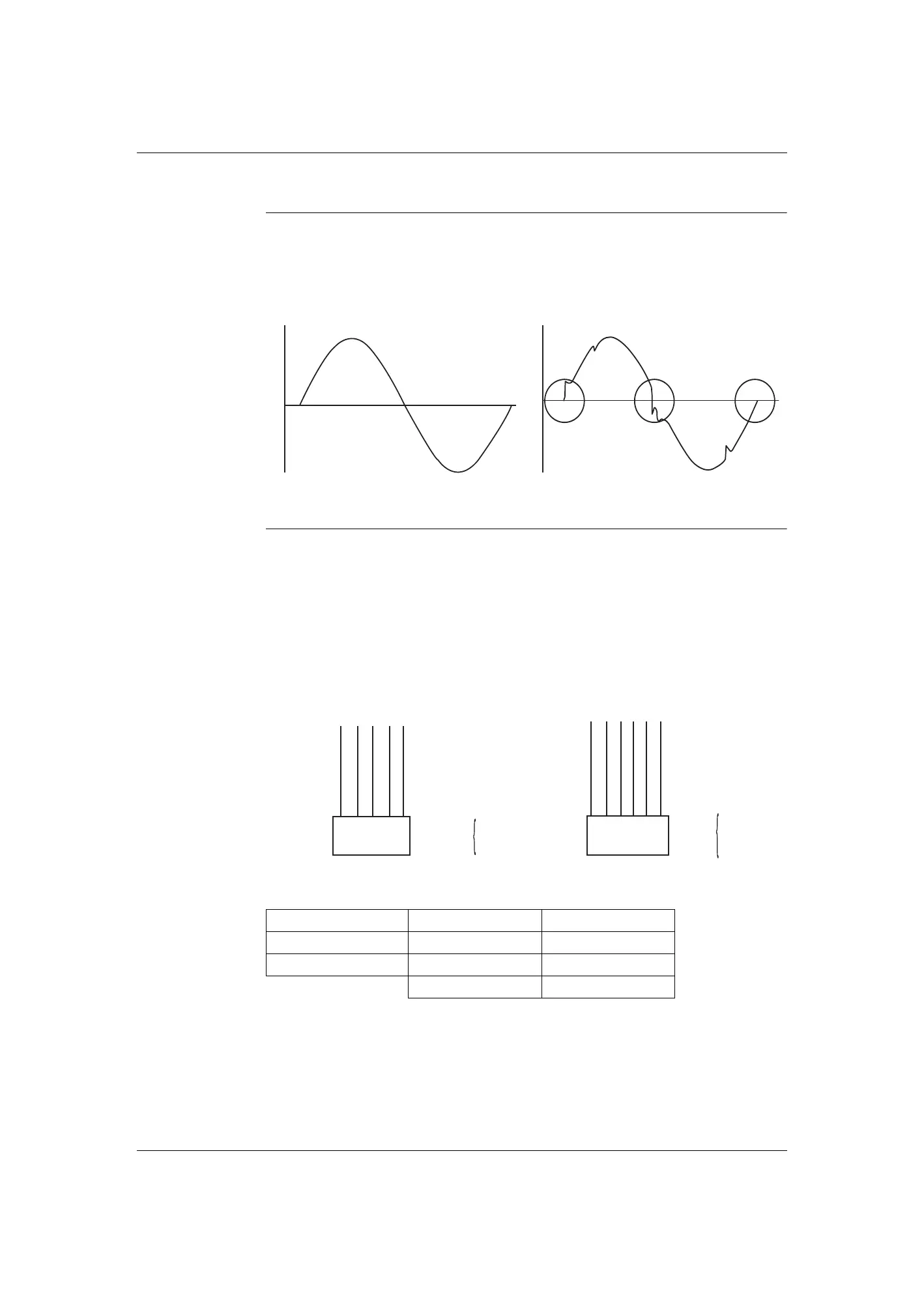
5.2 Power Supply Waveform Check
Check No.11 Measure the power supply waveform between No. 1 and No. 2 on the terminal strip, and check
the waveform disturbance.
Check if the power supply waveform is a sine wave (Fig.1).
Check if there is waveform disturbance near the zero-cross (sections circled in Fig.2).
5.3 Electronic Expansion Valve Check
Check No.12 Conduct the followings to check the electronic expansion valve (EV).
1. Check if the EV connector is correctly connected to the PCB.
2. Turn the power off and on again, and check if the EV generates a latching sound.
3. If the EV does not generate a latching sound in the step 2 above, disconnect the connector
and check the continuity using a multimeter.
4. Check the continuity between the pins 5 - 1, 5 - 2, 5 - 3, 5 - 4 (for 5P connectors) and
6 - 1, 6 - 2, 6 - 3, 6 - 4, 6 - 5, (for 6P connectors). If there is no continuity between the pins,
the EV coil is faulty.
5. If the continuity is confirmed in step 3, the outdoor unit PCB (main PCB) is faulty.
[Fig.1] [Fig.2]
Class 09/12 18/24
EV connector P/N 3S400001-1 A 3P606887-1
Coil Model Name CAM-M012DM DPFX07-274
5P 5 wires 6P 6 wires
Harness 5P
5P Connector
CheckS20
5 - 1
5 - 2
5 - 3
5 - 4
1 2 3 4 5
Harness 6P
6P Connector
Check
6 - 1
6 - 2
6 - 3
6 - 4
6 - 5
1 2 3 4 5 6
 Loading...