Actuator Check DAMA-SM-21-001
87 Service Diagnosis
5. Actuator Check
5.1 Thermistor Resistance Check
Check No.01 Measure the resistance of each thermistor using multimeter.
The resistance values are defined by below table.
If the measured resistance value does not match the listed value, the thermistor must be
replaced.
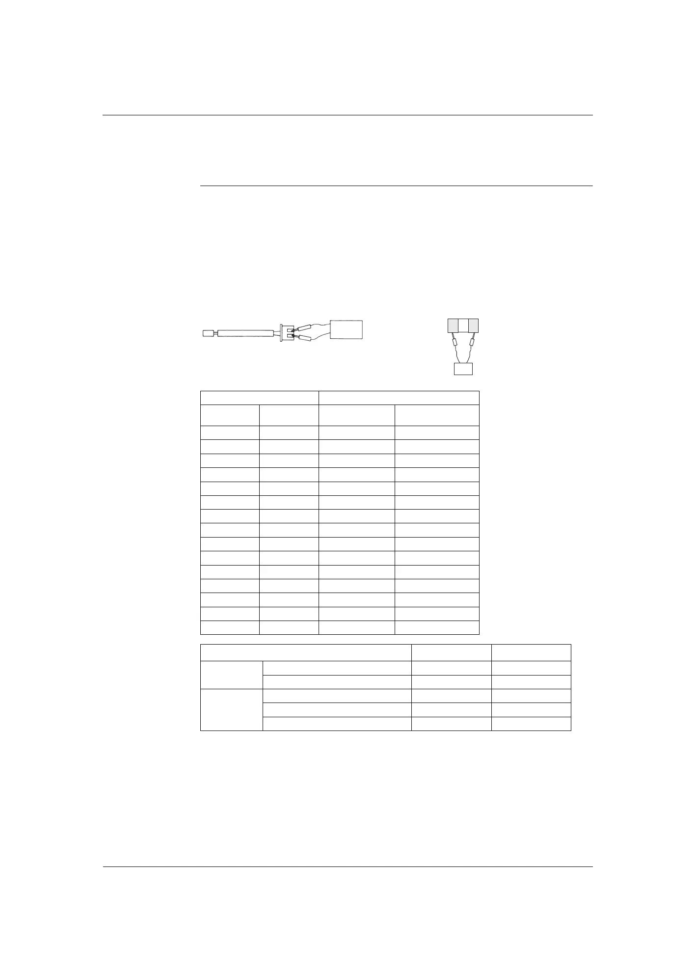
Disconnect the connector of thermistor ASSY from the PCB to measure the resistance
between the pins using multimeter.
To check the thermistor soldered on a PCB, disconnect the PCB from other PCB/parts, and
measure the resistance between the both ends of soldered thermistor.
Tolerance resistance type A : ±5%
Tolerance resistance type B : ±2%
Multimeter
Resistance range
Thermistor ASSY Soldered thermistor
Multimeter
Thermistor temperature (°C) Resistance (kΩ)
°C °F
Room temperature
thermistor
Room temperature
thermistor
-20 -4 73.4 197.8
-15 5 57.0 148.2
-10 14 44.7 112.1
-5 23 35.3 85.60
0 32 28.2 65.93
5 41 22.6 51.14
10 50 18.3 39.99
15 59 14.8 31.52
20 68 12.1 25.02
25 77 10.0 20.00
30 86 8.2 16.10
35 95 6.9 13.04
40 104 5.8 10.62
45 113 4.9 8.707
50 122 4.1 7.176
Thermistor Resistance Type R (25°C) or (77°F)
Indoor Unit
Room temperature thermistor B 10 kΩ
Indoor heat exchanger thermistor B 10 kΩ
Outdoor Unit
Outdoor temperature thermistor A 20 kΩ
Outdoor heat exchanger thermistor A 20 kΩ
Discharge pipe thermistor A 20 kΩ
 Loading...