RA Indoor Unit SiBE121123_A
117 Remote Controller
1.6 FVXG25/35/50K2V1B
Reference Refer to the following pages for detail.
Note: Refer to the operation manual of applicable model for detail. You can download operation
manual from ‘DISTRIBUTOR’S PAGE’:
DISTRIBUTOR’S PAGE → Product Information → Operation/Installation Manual
(URL: http://global.daikin.com/Daikin/global/Distributors_admin/user_mng/login.php
)
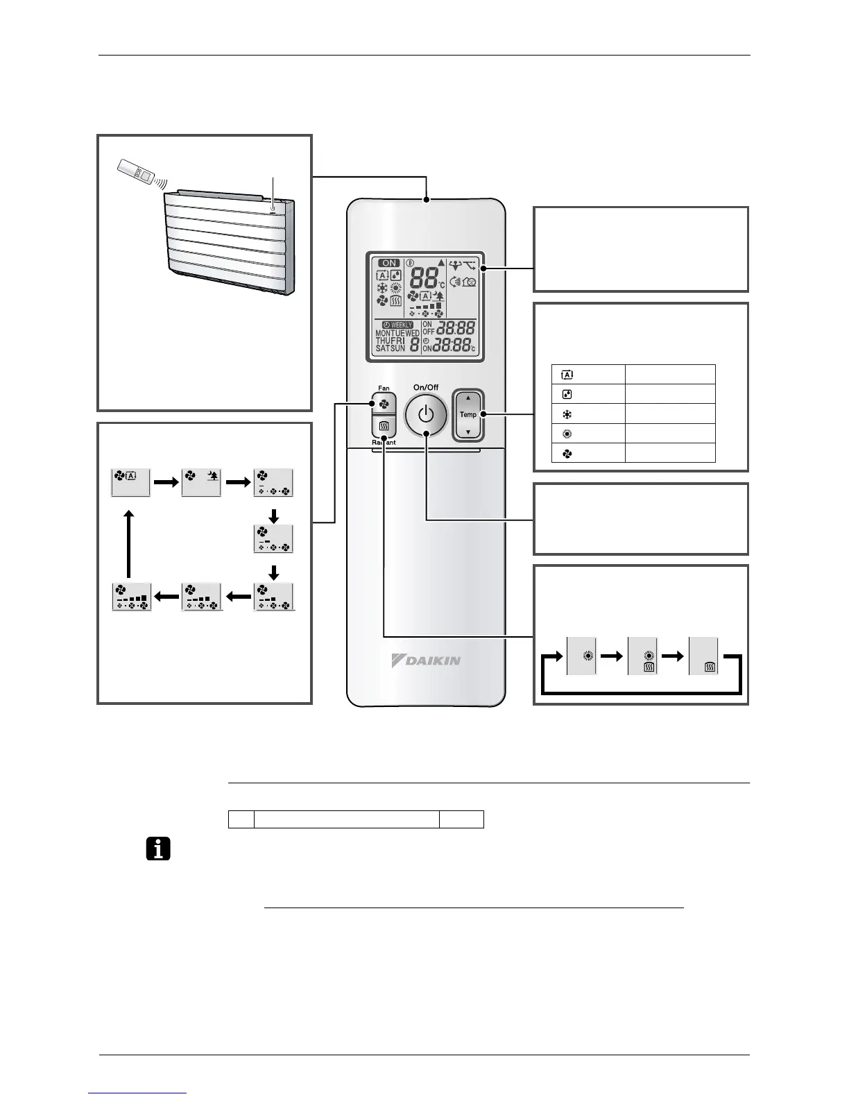
Signal transmitter
RADIANT
1
button
• Selects RADIANT operation.
Display (LCD)
• Changes the temperature setting.
ON/OFF button
Auto Indoor unit quiet Low
Middle low
MiddleMiddle highHigh
• Press this button once to start
operation.
Press once again to stop it.
TEMPERATURE
adjustment buttons
: AUTO
: DRY
: COOL
: HEAT
: FAN
18 ~ 30 °C
Not available
18 ~ 32 °C
10 ~ 30 °C
Not available
• Displays the current settings.
(In this illustration, each section is
shown with all its displays on for the
purpose of explanation.)
• To use the remote controller, aim the
transmitter at the indoor unit. If there
is anything to block signals between
the unit and the remote controller,
such as a curtain, the unit will not
operate.
• The maximum distance for
communication is approx. 7m.
FAN setting button
• In indoor unit quiet operation,
operation sound becomes weak.
(The airflow rate also decreases.)
• In DRY operation, the airflow rate
setting is not available.
• Selects the airflow rate setting.
(R18348)
Receiver
HEAT RADIANT1 RADIANT2
• This button can be used only in the
HEAT operation mode.
< ARC466A2 >
1 RADIANT operation P.60