EasyManua.ls Logo

Daikin FTXS35K2V1B Service Manual

Daikin FTXS35K2V1B
267 pages
To Next Page IconTo Next Page
To Previous Page IconTo Previous Page
Page #196 background imageLoading...
Page #196 background image
Troubleshooting for Outdoor Unit SiBE121123_A
185 Service Diagnosis
7.4 Unspecified Voltage (between Indoor Unit and Outdoor
Unit) / Anti-icing Control in Other Room
Error Code
UA, UH
Method of Error
Detection
A wrong connection is detected by checking the combination of indoor and outdoor units on the
microcomputer.
Error Decision
Conditions
Anti-icing control in other room
Unspecified internal and/or external voltages
Mismatching of indoor and outdoor units
Supposed
Causes
Anti-icing control in other room
Wrong models interconnected
Wrong indoor unit PCB or outdoor unit PCB mounted
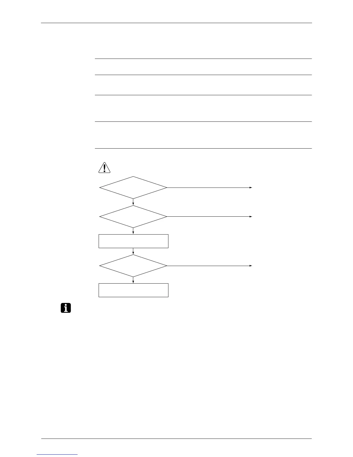
Troubleshooting
Note: Refer to “Anti-icing control for indoor unit” on page 186 for detail.
(R16018)
Caution
NO
YES
NO
YES
NO
YES
Check the model combination.
Check the combination of all the
models being connected.
The anti-icing function is
activated in other rooms.
Refer to A5.
Correct the supply voltage.
Match the compatible models.
Be sure to turn off the power switch before connecting or disconnecting
connectors, or parts may be damaged.
Error displayed while
operating?
Supply voltage as
specified?
Matched compatibly?

Table of Contents

Other manuals for Daikin FTXS35K2V1B

Questions and Answers:

Daikin FTXS35K2V1B Specifications

General IconGeneral
TypeSplit System
Cooling Capacity3.5 kW
Heating Capacity4.0 kW
Energy Efficiency Ratio (EER)3.21
Power Supply220-240V, 50Hz
Indoor Unit Dimensions (WxHxD)800 x 290 x 215 mm
Outdoor Unit Dimensions (WxHxD)800 x 550 x 285 mm
RefrigerantR32
Noise Level (Outdoor Unit)48 dBA
Seasonal Energy Efficiency Ratio (SEER)6.10

Summary

Part 1 List of Functions

1. Functions

Lists and categorizes various functions of indoor units, including basic, comfort, operation, and lifestyle features.

Part 2 Specifications

1. Indoor Unit

Provides detailed technical specifications for various wall-mounted, floor-standing, and cassette indoor units.

2. Outdoor Unit

Lists technical specifications for outdoor units, including models, dimensions, power, and refrigerant details.

Part 3 Printed Circuit Board Connector Wiring Diagram

1. Indoor Unit

Details PCB layout and connector assignments for various indoor unit models.

2. Wired Remote Controller

Provides PCB layout and connector details for wired remote controllers like BRC1D528 and BRC1E51A7.

3. Wireless Remote Controller

Details PCB layout and connector assignments for wireless remote controllers like BRC7E530W.

4. Outdoor Unit

Details PCB layout and connector assignments for outdoor units.

Part 4 Function and Control

1. Function of RA Indoor Unit

Explains various functions of RA indoor units, including temperature, airflow, and special modes like RADIANT.

2. Function of SA Indoor Unit

Details functions specific to SA indoor units, such as drain pump control and thermostat behavior.

3. Function of Thermistor

Describes the role and location of various thermistors used for temperature sensing and control.

4. Control Specification

Outlines system control logic, including mode hierarchy, frequency control, and protection functions.

Part 5 Remote Controller

1. RA Indoor Unit

Describes the operation and features of remote controllers for RA indoor units, including button functions.

2. SA Indoor Unit

Details the operation and features of remote controllers for SA indoor units, including BRC1D528 and BRC1E51A7.

Part 6 Service Diagnosis

1. Troubleshooting with LED

Guides troubleshooting based on indoor and outdoor unit LED indicators and error codes.

2. Problem Symptoms and Measures

Provides a table of common problem symptoms and their corresponding checks and measures.

3. Service Check Function

Explains how to enter and use service check modes on remote controllers for diagnosis.

4. Code Indication on Remote Controller

Lists error codes displayed on remote controllers for RA, SA, and Outdoor units.

5. Troubleshooting for RA Indoor Unit

Provides detailed troubleshooting steps for various RA indoor unit abnormalities.

6. Troubleshooting for SA Indoor Unit

Details troubleshooting procedures for SA indoor unit abnormalities like PCB, drain, and fan motor issues.

7. Troubleshooting for Outdoor Unit

Outlines troubleshooting steps for common outdoor unit errors like refrigerant shortage and voltage issues.

8. Check

Lists various component checks, including thermistors, fan motors, and PCB diagnostics.

Part 7 Trial Operation and Field Settings

1. Pump Down Operation

Explains the procedure for pump down operation, essential for refrigerant handling during relocation.

2. Forced Cooling Operation

Describes how to perform forced cooling operation for specific maintenance tasks.

3. Trial Operation

Details the procedure for conducting trial operation to verify system functionality after installation.

4. Field Settings

Guides on setting parameters for indoor units based on model type and installation configuration.

5. Silicon Grease on Power Transistor / Diode Bridge

Instructions on applying silicon grease during PCB replacement for proper heat dissipation.

Part 8 Appendix

1. Piping Diagrams

Visual representation of refrigerant and field piping connections for various indoor and outdoor units.

2. Wiring Diagrams

Electrical wiring diagrams for indoor and outdoor units, showing component connections.

3. Removal Procedure (Booklet No.)

Information on obtaining separate booklets for detailed component removal procedures.

Related product manuals