Check SiBE121123_A
207 Service Diagnosis
8.2 Fan Motor Connector Output Check
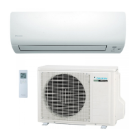
Check No.02 FTXG, FTXS35/42/50K, FTXS-J, ATXS, FVXG, FVXS Series
1. Check the connection of connector.
2. Check motor power supply voltage output (pins 4 - 7).
3. Check motor control voltage (pins 4 - 3).
4. Check rotation command voltage output (pins 4 - 2).
5. Check rotation pulse input (pins 4 - 1).
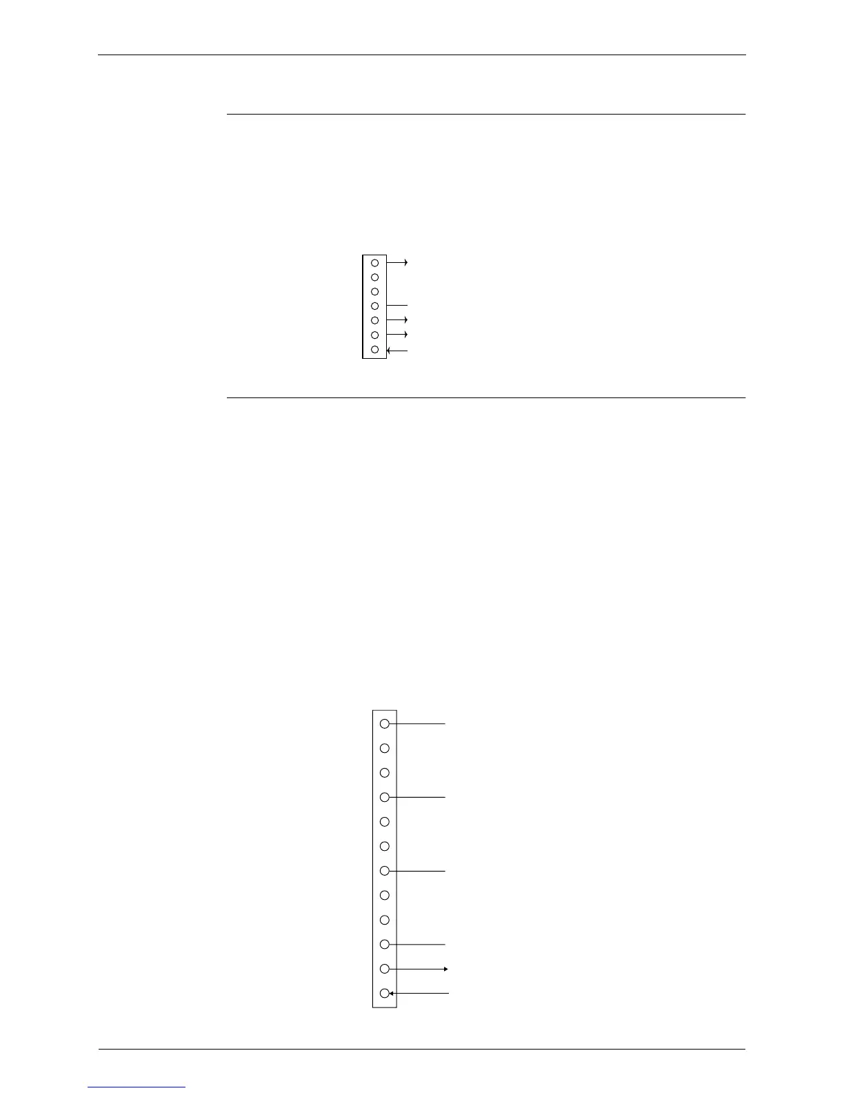
Check No.03 CTXS, FTXS20/25K, FTX, ATX Series
Fan motor wire breakdown / short circuit check
1. Check the connector for connection.
2. Turn the power off.
3. Check if each resistance at the phases U - V and V - W is 90
Ω
~ 100
Ω
(between the pins
12 - 9, and between 9 - 6).
Motor control voltage check
1. Check the connector for connection.
2. Check the motor control voltage is generated (between the pins 2 - 3).
Rotation pulse check
1. Check the connector for connection.
2. Turn the power on and stop the operation.
3. Check if the Hall IC generates the rotation pulse 4 times when the fan motor is manually
rotated once (between the pins 1 - 3).
7
6
5
4
3
2
1
Motor power supply voltage (310 ~ 340 VDC)
Unused
Unused
GND
Motor control voltage (15 VDC)
Rotation command voltage (1~ 5 VDC)
Rotation pulse input
S1 or S200
(R14225)
(R11979)
12
11
10
9
8
7
6
5
4
3
2
1
Phase U
Free pin
Free pin
Free pin
Free pin
Free pin
Free pin
Phase V
Phase W
GND
Motor control voltage (15 VDC)
Rotation pulse (5 VDC)
S200
 Loading...


