InsTallaTIon
www.DaikinApplied.com 21 IOM 1266-2 • MAGNITUDE
®
MODEL WME CHILLERS
Field Insulation
If the optional factory installation of thermal insulation is not
ordered, insulation should be eld installed to reduce heat
loss and prevent condensation from forming. Insulation should
cover:
• the evaporator barrel, tube sheet, and waterboxes.
• the suction line from the top of the evaporator to the
compressor inlet ange.
• the compressor support brackets welded to the
evaporator.
• the liquid line from the expansion valve to the evaporator
inlet, including the expansion valve.
• the part load balance valve to the evaporator.
Approximate total square footage of insulation surface required
for individual packaged chillers is tabulated by evaporator code
and can be found in Table 8.
Table 8: Insulation Area Required for WME Models
Evaporator Code
Insulation Area
sq. ft. (m
2
)
E3012 115 (10.6)
E3612 129 (11.9)
E4216 263 (24.4)
E4816 302 (28.1)
Field Power Wiring
The standard power wiring connection to Magnitude
®
chillers
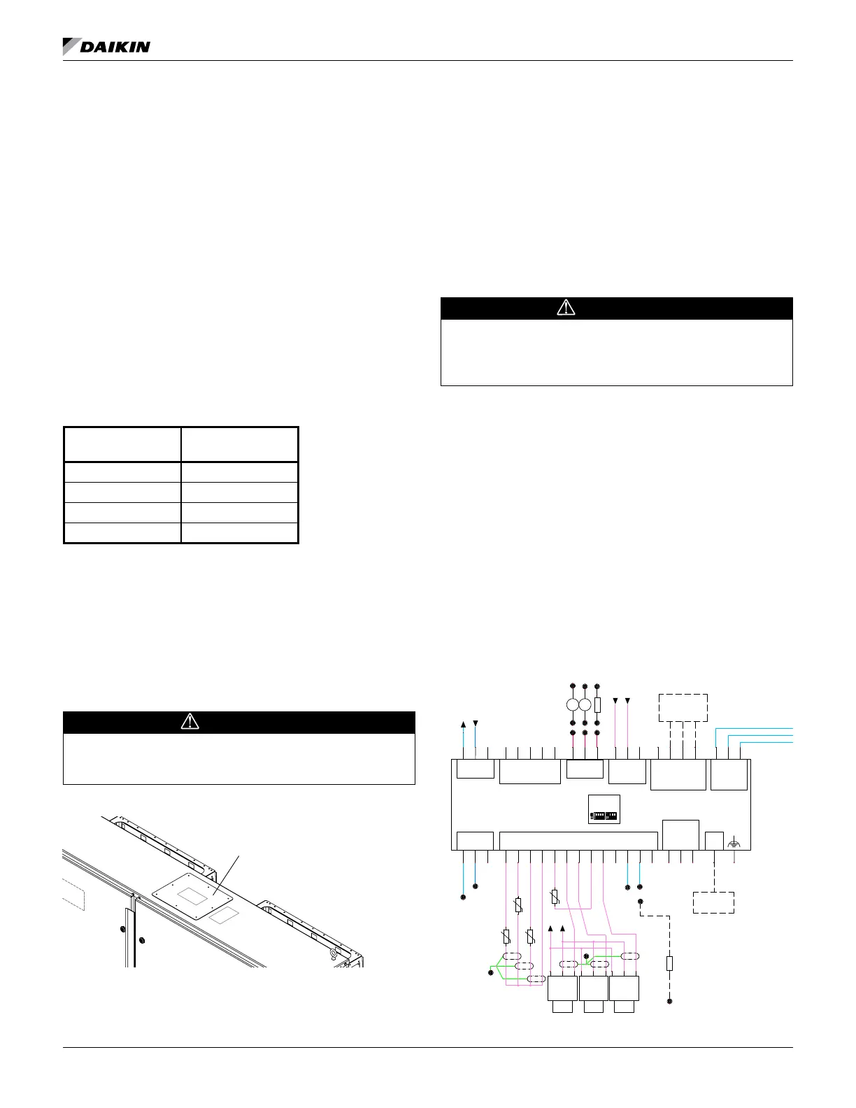
is multi-point for dual compressor WME models. Power conduit
entry will be at the top of the unit power panel; see Figure 21
for general reference as power entry cover plate location will
vary by unit conguration. Copper or aluminum wiring may
be used for power wiring. Refer to the unit nameplate and the
Daikin Tools selection report for the correct electrical ratings.
DANGER
Qualied and licensed electricians must perform wiring. An
electrical shock hazard exists that can cause severe injury
or death.
Figure 21: Unit Power Connection Point
Factory-mounted and wired line reactors are standard. The
eld control wiring required varies depending on unit model.
See “Figure 24: WME Field Wiring Schematic” on page 23
for wiring information. These wiring diagrams are also provided
with the chiller.
NOTE: Wiring, fuse, and wire size must be in accordance
with the National Electrical Code
®
(NEC). The voltage
to these units must be within ±10% of nameplate
voltage (415V units must have voltage within -13%
and +6% of nameplate voltage) and the voltage
unbalance between phases must not exceed 2%.
Since a 2% voltage unbalance will cause a current
unbalance of 6 to 10 times the voltage unbalance per
the current version of the NEMA MG-1 Standard, it is
most important that the unbalance between phases
be kept at a minimum.
CAUTION
Do not use power factor correction capacitors with WME
chillers. Doing so can cause harmful electrical resonance in
the system. Correction capacitors are not necessary since
VFDs inherently maintain high power factors.
See “Use with On-Site Generators” on page 51 for additional
information on Generator Sizing and Transferring Power.
Chiller Control Power
In all cases of power operation except when with
RapidRestore
®
, the chiller control power must remain as
factory-wired from a unit-mounted power supply.
BAS Connection
If BAS module is needed for BACnet
®
or Modbus, the UE1
module will be replaced with the BUE1 module shown in Figure
22 for wiring. When Lon protocol is used the UE1 module
remains and a Lon card is connected to the Unit controller in
the BMS CARD port.
Figure 22: BAS Module Wiring Schematic
Power Entry Cover Plate -
Remove to cut hole in
cover plate for conduit
and then replace.
REVISIONPART NUMBER
1
2
3
336078102 0A
WME-C UNIT BOX SCH
WHT(2)
RED(2)
GRN(2)
BLK(2)
S+
S-
REF
OPEN
B
W
G
R
24V+
24V-
ON
1234 5678
EXVDRV
111111
L2
11
L2
20
ACT2
ACT1
PC RESET
22
BA
35
LONMARK WIRING
GND
BLK
33
23
BLK
BLU
BRN
WHT
+24VAC/DC
24N
CEFS
BLU
33
23
23
BLK
BRN
WHT
+24VAC/DC
24N
EEFS
23
21
SW1 (UNIT SWITCH)
3
4
WHT
WHT
WHT
SWITCH
31
22
31
REMOTE
PWR
INPUT
TOWER STAGE #3
6
TOWER STAGE #2
CONDENSOR PUMP #2
54
TOWER STAGE #1
TS1
CP2
654
EVAP PUMP #1
EVAP PUMP #2
321
L1
L1
321
CB1
6A
EP2
EP1
30
29
BLK
32
20
35
35
0-10V
COOLING TOWER VFD
0-10V
COOLING TOWER BYPASS VALVE
3029
RED
28
PE
7
7
TS3
TS2
36
36
13
121212
CONDENSOR PUMP #1
CP1
-
+
34
22
E-PORT1
CMPR BOX #1
OR MODBUS
FOR BACNET-MSTP
FIELD WIRING
ADAPTER
SEE DWG 336078103
E-PORT2
CMPR BOX #2
BACNET-IP
FIELD WIRING
34
(SCALE: 0-125% RLA)
0-10V
UNIT MOTOR CURRENT OUTPUT
VDC OR VAC
NC
NO
ALARM NO/NC
AR4
24/120V
RED(3)
BLK(3)
10
8
9
SENSOR
SENSOR
10
8
9
EXV BOARD CAL
AR3
24
WHT
WHT
BLK
RED
PWR
GND
SIG
LLP
PE
PWR
GND
SIG
EVPP
PWR
GND
SIG
CNDP
BLK(3)
RED
RED
RED
32
21
PE
Address = 1
G
G0
Vbat
U2
U1
U3
GND
U4
U5
U6
GND
U7
U8
U9
U10
GND
NO1
C1/2
NO2
NO3
C3/4/5
NO4
C3/4/5
NO5
NO6
NC6
C6
J1
J2
J10
J11
J12
EHUB
J9
+5Vref
GND
+Vdc
MODBUS
ON
1
234 1234
UE1
Tx-/Rx-
Tx+/Rx+
GND
TxL/RxL
TxH/RxH
GND
J5 CAN
+Vtwrm
Tx-/Rx-
Tx+/Rx+
GND
J3 DISP
J4 FBus
(OPTION)
BUE1
25
25
S1
HMI
PC1
24/120VAC
Customer
CUSTOMER SUPPLIED POWER
J5
C1
J3
T
U3
GND
+VD
C
J2
J12
NO1
U4
GND
U5
GND
Y1
VG0
VG
Y2
Y3
Y4
BMS CARDFIELD BUS CARD
ID1
J4
NO2
C1
C4
C4
NO4
NO5
NO6
NO3
J13
C7
C7
NO7
NO8
NC8
J25 BMS2
+
GND
-
C8
J14
-
GND
+
J26 FBus2
ID2
ID3
ID4
ID5
ID6
ID7
ID8
IDC1
J15
UC1
01-10
01-4
01-10
01-4
01-2
01-2
01-9
01-5
24-18
24N-8
USB
24N-7
24-8
120N-1
GRN
WHT
RED
BLK
24-18
24-23
24N-3
SW-2
UC1:ID7
-
+
-
+
U
C
1
:
I
D
7
U
C
1
:
I
D
6
2
4
-
9
SW-1
1
2
0
-
9
120-10
1
2
0
-
8
1
2
0
-
7
120-6
1
2
0
-
1
1
2
0
-
5
1
2
0
-
4
1
2
0
-
3
1
2
0
-
2
2
4
-
7
2
4
-
8
2
4
N
-
2
2
4
-
5
2
4
-
4
1
2
0
-
1
1
2
4
N
-
1
0
2
4
-
1
9
2
4
N
-
9
2
4
N
-
1
1
ETR3
V
G
A
ETR4
24-15
24-16
24-17
1
2
0
-
1
3
1
2
0
-
1
4
1
2
0
-
1
2
G
N
D
+
5
V
2
4
N
-
7
2
4
-
1
1
2
4
-
1
4
2
4
-
1
3
+
5
V
G
N
D
2
4
-
1
2
2
4
N
-
4
E
T
R
2
U
C
1
:
I
D
6
S
W
-
1
01-10
01-5
2
4
-
1
1
+
+
2
4
-
6
2
4
-
2
0
UP TO 4 ACTUATORS
SEE PAGE 2 FOR
SECT 2
RM/POWER WIRING
11 12 13
UTB1 TERMINAL BLOCK JUMPERS
NEUTRAL BLOCK
98
1065 732 41
EEWT
ELWT
CEWT
CLWT
LLT
01-12
01-12
01-5
01-2
01-3

 Loading...


