 Loading...
Do you have a question about the Daikin Magnitude WME Series and is the answer not in the manual?
| Refrigerant | R-134a |
|---|---|
| Dimensions (LxWxH) | Varies by model |
| Weight | Varies by model |
| Type | Water-Cooled Chiller |
| Compressor Type | Centrifugal |
| Energy Efficiency Ratio (EER) | Up to 14.0 |
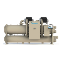
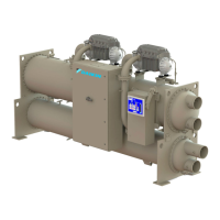
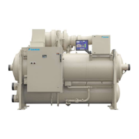
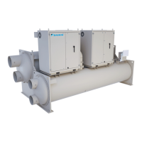
Provides an overview of the Daikin Magnitude® Centrifugal Chillers, highlighting their features and design.
Details the MicroTech® control system, including the HMI, unit controller, and compressor controllers.
Describes the location and purpose of various identification nameplates on the chiller unit.
Provides instructions for inspecting and handling the chiller unit upon receipt.
Specifies recommended location requirements and environmental conditions for chiller installation.
Outlines procedures and precautions for storing new or inoperative chillers.
Details minimum clearance requirements around the unit for proper installation and service.
Describes requirements for mounting the unit on a suitable base and ensuring it is level.
Presents dimensional drawings and weight specifications for various WME models.
Explains disassembly options for tight installation clearances and bolt-together construction.
Details the construction where components are removed and shipped separately for reassembly.
Provides dimensional diagrams for typical WME knockdown configurations.
Lists dimensions and weights for WME compressors based on model.
Details requirements and safety precautions for rigging and lifting compressors.
Provides step-by-step procedures for removing and re-attaching a chiller compressor.
Covers requirements for field-installed water piping, including material and connection types.
Discusses methods for controlling condenser water temperature for optimal chiller performance.
Explains the function and installation of pressure relief valves for safety.
Provides guidance on field-installing thermal insulation to reduce heat loss and prevent condensation.
Details standard power wiring connections and electrical considerations for the chiller.
Explains features that allow quick restart and operation during power loss events.
Illustrates field wiring connections for power, options, and control systems.
Highlights the operator's role in understanding and maintaining the chiller's operation.
Details the general sequence of chiller operation for single and dual compressor units.
Describes the HMI's functions, navigation, and operation, including without the HMI.
Explains how to use HMI setpoint screens to adjust various operational parameters.
Provides a step-by-step guide on how to change setpoints using the HMI interface.
Describes the types of alarms (Critical and Warning) and how they are indicated and managed.
Explains the process for clearing alarms, auto-clear conditions, and the implications of manual clearing.
Lists the analog and digital inputs/outputs for the unit controller.
Details the analog inputs and digital outputs for each compressor controller.
Covers integration with BAS, available protocols, and communication module options.
Discusses chiller compatibility with on-site generators, including sizing and power transfer.
Instructions for inspecting the chiller and completing pre-start checklist before startup.
Details the installation, wiring, and calibration procedure for the thermal dispersion flow switch.
Covers essential maintenance tasks including cleaning, electrical checks, and component inspection.
Provides procedures for preparing the chiller for seasonal shutdown, including draining water.
Outlines the steps required for seasonal startup, including leak testing and electrical checks.
Presents a recommended maintenance schedule with frequencies for various procedures.
Provides definitions for technical terms and acronyms used throughout the manual.
Presents the R-134a refrigerant temperature/pressure chart for reference.
Information on obtaining parts, service, and training from Daikin Applied.


