operaTIon
www.DaikinApplied.com 49 IOM 1266-2 • MAGNITUDE
®
MODEL WME CHILLERS
Controller Inputs and Outputs
As outlined below, inputs and outputs vary between the unit
controller and the compressor controller.
Unit Controller Inputs and Outputs
The following tables list the unit controller inputs and outputs,
both analog and digital, as well as the stepper motor outputs.
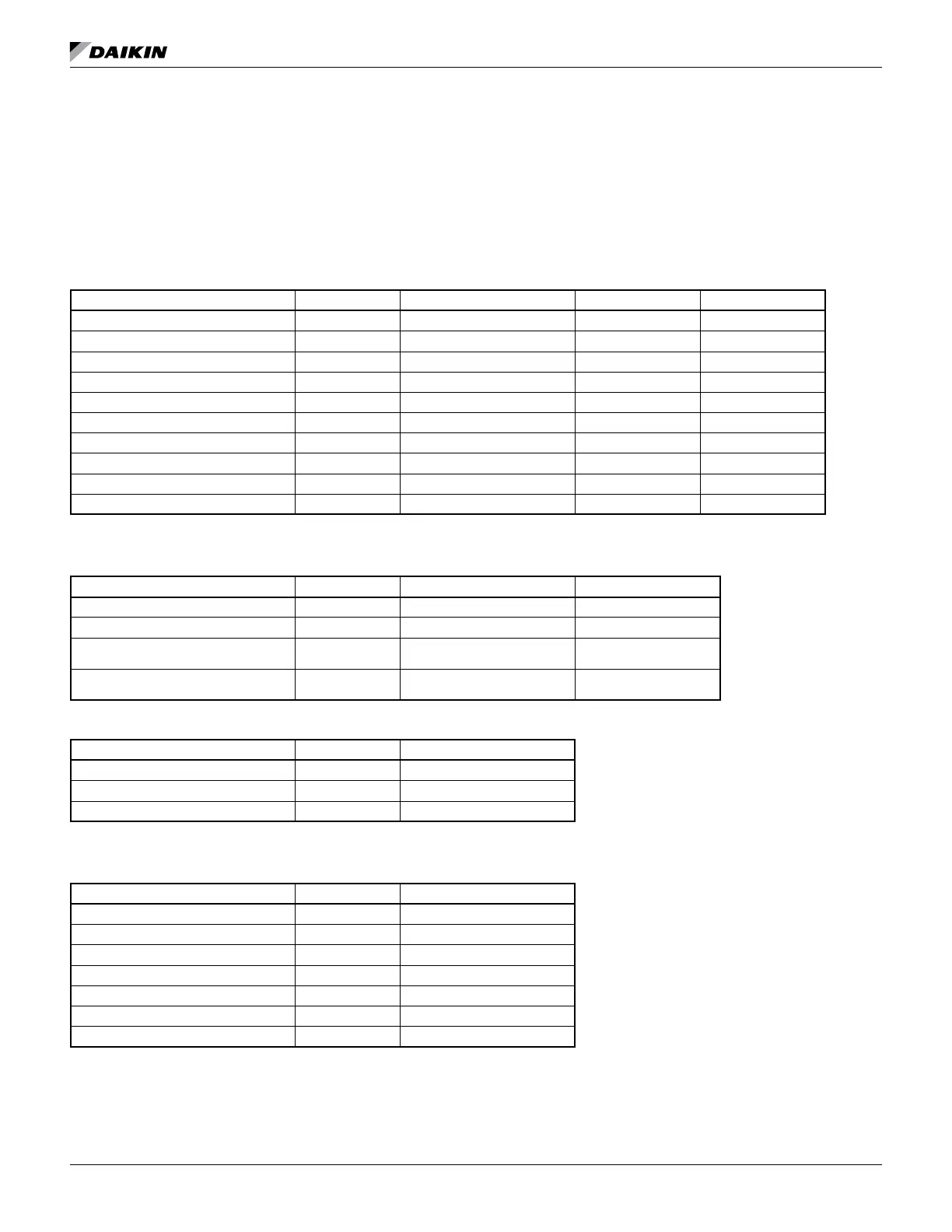
Table 25: Unit Controller, Analog Inputs
Description Wiring Source Signal Sensor Range
Entering Evaporator Water Temperature Chiller NTC Thermistor 10k @ 25°C -40 to 125°C
Leaving Evaporator Water Temperature Chiller NTC Thermistor 10k @ 25°C -40 to 125°C
Entering Condenser Water Temperature Chiller NTC Thermistor 10k @ 25°C -40 to 125°C
Leaving Condenser Water Temperature Chiller NTC Thermistor 10k @ 25°C -40 to 125°C
Liquid Line Refrigerant Temperature Chiller NTC Thermistor 10k @ 25°C -40 to 125°C
Evaporator Refrigerant Pressure Chiller Sealed Gage Transducer 0.5 to 4.5 VDC nominal 0 to 100 psi
Liquid Line Refrigerant Pressure Chiller Sealed Gage Transducer 0.5 to 4.5 VDC nominal 0 to 200 psi
Condenser Refrigerant Pressure Chiller Sealed Gage Transducer 0.5 to 4.5 VDC nominal 0 to 200 psi
Reset of Leaving Water Temperature Field BAS 4 to 20 mA Current 0 to 100%
Demand Limit Field BAS 4 to 20 mA Current 0 to 100%
NOTE: “Sensor Range” in Table 25 indicates the range of the input, NOT the operating range of the chiller.
Table 26: Unit Controller, Digital Inputs
Description Wiring Signal Source States (Open/Closed)
Front Panel “Stop/Auto” Switch Chiller Isolated Switch Contacts Stop/Auto
Remote Start/Stop Field Isolated Switch or Relay Contacts Stop/Auto
Evaporator Water Flow Switch
Chiller & Field
(in series)
Isolated Flow Switch Contacts No Flow/Flow
Condenser Water Flow Switch
Chiller & Field
(in series)
Isolated Flow Switch Contacts No Flow/Flow
Table 27: Unit Controller, Analog Outputs
Description Output Signal Sensor Range
EXV Driver Signal 0 to 10 VDC 0 to 100% Open
Cooling Tower Bypass Valve Position 0 to 10 VDC 0 to 100% Open
Cooling Tower VFD Speed 0 to 10 VDC 0 to 100%
NOTE: “Sensor Range” in Table 27 indicates the range of the output, NOT the operating range of the chiller.
Table 28: Unit Controller, Digital Outputs
Description Load Rating
Alarm Indicator Light 240 VAC
Evaporator Water Pump #1 Pump Contactor 240 VAC
Evaporator Water Pump #2 Pump Contactor 240 VAC
Condenser Water Pump #1 Pump Contactor 240 VAC
Condenser Water Pump #2 Pump Contactor 240 VAC
Cooling Tower Fan #1 Fan Contactor 240 VAC
Cooling Tower Fan #2 Fan Contactor 240 VAC

 Loading...


