OM 1280-2 • MICROTECH UNIT CONTROLLER 22 www.DaikinApplied.com
Chilled Water Valve Control
it is operated by a proportional actuator. The modulating valve
actuator contains a spring that ensures that the chilled water
valve is closed upon loss of power. Each proportional actuator is
driven by the UVC using 0-10VDC outputs (scaled to 2-10VDC).
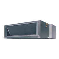
Figure 15: Cool State Operation - Valve Control
The 2-way modulating chilled water valve is furnished to
fail closed to the coil. 24VAC is required to power the valve
actuator. When the actuator is powered, a controller will
provide a 2-10VDC signal to the actuator. A signal of 2VDC or
less will drive the valve closed; the valve will drive open as the
signal increases to a maximum of 10VDC.
If 24VAC is lost to the actuator, valve will spring-return to its fail
position (closed to the coil for chilled water valves).
The 3-way modulating chilled water valve is furnished to
fail closed to the coil. 24VAC is required to power the valve
actuator. When the actuator is powered, a controller will
provide a 2-10VDC signal to the actuator. A signal of 2VDC or
less will drive the valve closed (bypassing coil); the valve will
drive open as the signal increases to a maximum of 10VDC
If 24VAC is lost to the actuator, valve will spring-return to its fail
position (closed to the coil for chilled water valves, full bypass
around the coil).
Chilled Water Face and Bypass Damper
and End of Cycle Valve Control
CAUTION
Both a wet-heat end-of-cycle (EOC) valve and a chilled water end-of-cycle
(EOC) valve are strongly recommended by Daikin. If an EOC valve is not
installed, it is likely that over-heating or over-cooling of the space will occur.
wet heat end-of-cycle (EOC) valve and/or a two-position,
normally closed chilled water end-of-cycle valve. The two-
position valve actuators contain springs that ensures that the
wet heat valve is open and the chilled water valve is closed
upon loss of power. The two-position actuators are driven by the
UVC using one binary output per actuator.
Face and Bypass (F&BP) dampers are used in conjunction with
for a face and bypass damper operated by a proportional
actuator. The proportional actuator is driven by the UVC using a
0-10VDC output (scaled to 2-6VDC).
When the F&BP damper is used with an EOC valve, the F&BP
damper maintains the DATS. When there is no call for hydronic
a Valve Freeze Protect condition, in which case the valve will
go full open and the F&BP damper will be used to maintain the
control temperature.
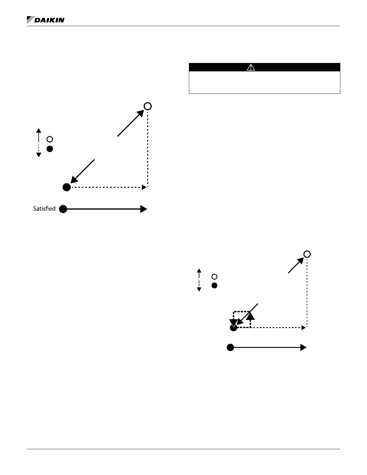
Figure 16: Cool State Operation – Face and Bypass
Damper Control
Discharge Air
0%
100%
Valve Position
Cooling
Capacity
Warmer
SatLo
SatHi
Staging
Down
Staging
Up
EOC Valve Open –
EOC Valve Closed –
Discharge Air
0%
100%
F&BP Damper Position
Primary
Cooling
Capacity
WarmerSatisfied
SatLo
SatHi
Staging
Down
Staging
Up
 Loading...