OM 1280-2 • MICROTECH UNIT CONTROLLER 29 www.DaikinApplied.com
Additional Occupancy Features
Network Occupancy Sensor Capability
A networked occupancy sensor can be interfaced with the
Occupancy Sensor Input variable to select occupancy modes.
When the Occupancy Sensor Input variable is used, it automatically
overrides any hard-wired unoccupied binary input signal.
Internal Daily Schedule
capable of two occupied times and two unoccupied times for
each of the seven days of the week, and one holiday schedule.
This internal schedule can be overridden through the LUI
keypad or network communications accordance with Table 11
on page 27. The internal schedule is set up through the LUI
keypad or ServiceTools software.
The UVC’s real time clock maintains time through a power
cycle subject to the battery installed on the controller. If the
internal schedule is being used, it is recommended that
the battery be replaced every 2 years as part of a regular
maintenance program. See IM 1286 for more details.
Remote Wall-Mounted Sensor Tenant
Override Switch
The optional remote wall-mounted sensors include a tenant
override switch. This switch provides a momentary contact closure
that can be used by room occupants to temporarily force the UVC
into the bypass occupancy mode from unoccupied mode.
NOTE: The Occupancy Override Input can override the
tenant override feature. For example, if the network
uses the Occupancy Override Input to force the unit
into unoccupied mode, then the wall sensor tenant
override switch does not operate as expected.
Therefore, Daikin strongly recommends using the
Occupancy Sensor Input to control occupancy
modes over a network and only using the Occupancy
Override Input if there is reason to ensure tenant
override does not occur.
Remote Wall-Mounted Sensor Status LED
The optional remote wall-mounted sensors each include a UVC
status LED. This status LED aids diagnostics by indicating the
UVC occupancy mode and fault condition.
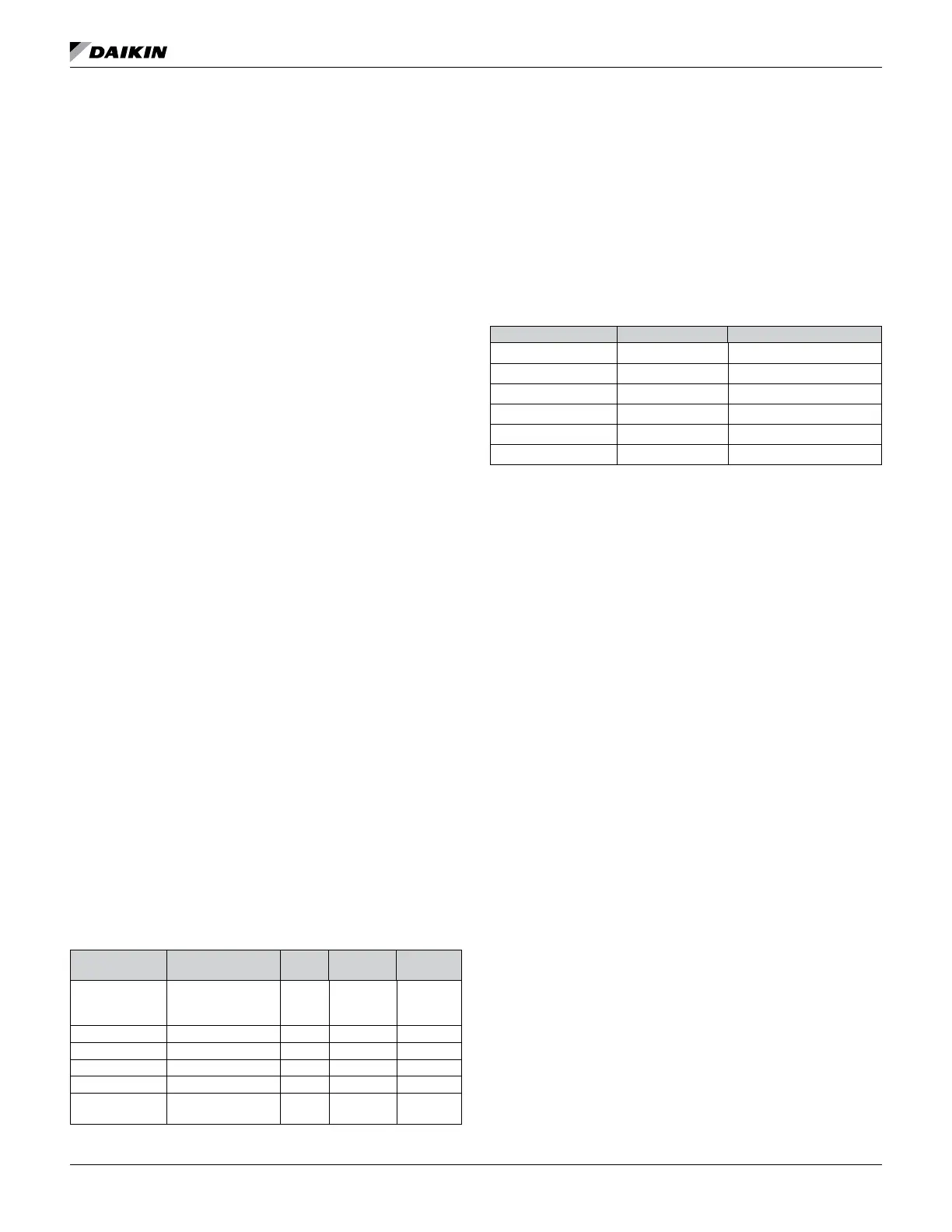
Table 12: Remote Wall-Mounted Sensor Status LED
Status LED
Mode
Condition Priority
LED On
Time (Sec)
Time (Sec)
ALARM_ACTIVE
Alarm Determines
Number of Flashes
1 0.3
0.3 (1.3
Between
Cycles)
WINK Network Wink Activity 2 3.0 3.0
SERVICE_TEST Service Test Mode 3 0.0 Continually
UNOCC Unoccupied Mode 4 0.5 5.5
Standby Mode 5 5.5 0.5
Occupied Bypass
Mode
6 Continually 0.0
Space Temperature Setpoints
The UVC uses the six occupancy-based temperature setpoints
occupancy mode, and the values of several network variables.
that the UVC maintains.
Table 13: Default Occupancy-Based Temperature Setpoints
Temperature setpoint Abbreviation Defaults
Unoccupied cool UCS 82.0°F (27.8°C)
Standby cool SCS 77.0°F (25.0°C)
Occupied cool OCS 73.0°F (22.8°C)
Occupied heat OHS 70.0°F (21.1°C)
Standby heat SHS 66.0°F (18.9°C)
Unoccupied heat UHS 61.0°F (16.1°C)
Network Setpoint Capability
The Setpoint Input variable is used to allow the temperature
setpoints for the occupied and standby modes to be changed
this variable.
by this variable. This variable is typically set bound to a
supervisory network controller or to a networked wall module
having a relative setpoint dial.
Use the keypad/display to make adjustments to the value
Calculations” on page 31.
NOTE:
most recent change to this variable will be the one
that is used.
 Loading...