www.DaikinApplied.com 41 OM 1280-2 • MICROTECH UNIT CONTROLLER
External Binary Outputs
The UVC has three binary outputs that provide the functions
described below.
Figure 24: Binary Outputs
These outputs are relay type outputs that are intended to be
used with signal level voltages (24VAC maximum) only. For
wiring examples, see MicroTech Unit Ventilator Controller IM
1286.
NOTE: Not all of the functions listed can be used at the same
be adjusted to select which function will be used for
these outputs when multiple functions are indicated
below.
External Binary Output 1
This relay output provides a normally open, normally closed,
and common set of connections that can be used to signal the
operation of the motorized valve or pump. The normally de-
energized output will energize on a call for heating or cooling.
The output will de-energize when the call for heating or cooling
goes away.
External Binary Output 2
This binary output can be used as a fault signal.
Fault Signal
This output provides 24VAC signal that can be used to signal
a fault condition. When a fault exists, the UVC energizes this
relay output. When the fault or faults are cleared, the UVC de-
energizes this relay output. This functionality can be reversed
through the LUI keypad or ServiceTools software.
External Binary Output 3
This output can be used to operate an auxiliary heat device or
signal exhaust fan operation.
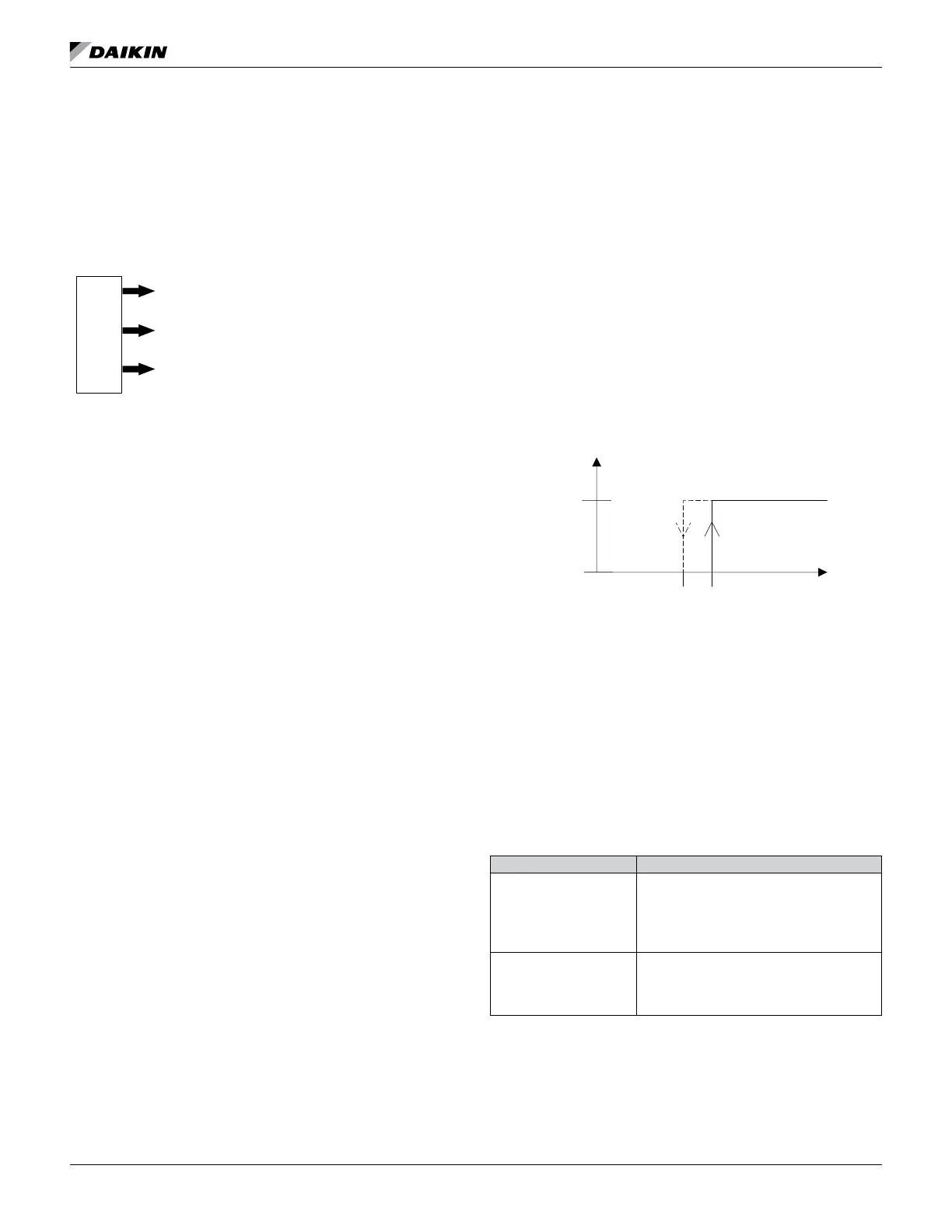
Exhaust Fan ON/OFF Signal
This relay output provides a 24VAC output that can be used
to signal the operation of an exhaust fan. The position of the
OA damper may be used to energize a 3rd party exhaust fan.
has a default value of (12%) to activate the exhaust fan when
the outside air damper opens to the minimum OA position,
(ncpOAMinPosExhaust). The exhaust fan output will de-
energize when the OA damper goes below the ncpExhStartPos
minus 5%.
Figure 25: Exhaust Fan Hystresis Diagram
Auxiliary Heat Signal
This output provides 24VAC signal that can be used to operate
operate a normally closed auxiliary heat device (energize when
heat is required), such as electric heat. However, the output
device (de-energize when heat is required), such as a wet heat
valve actuator with a spring setup to open upon power failure.
ServiceTools software.
Table 21: Auxiliary Heat Start/Stop Calculation
Start/Stop Calculation
Auxiliary heat starts when:
Heat PI-Loop = saturated high (100%) for more
than two minutes
AND
Auxiliary heat stops when:
UVC Input and Output Table
All UVC input and output connections and their corresponding
unit ventilator usage are shown in Table 22 on page 42.
BinaryOutputs
3relay type outputsw/signal voltage
Output 1: Pump or Motorized Valve
Output 2: Fault signal
Output 3:
Exhaust fan operation (default)
or Auxiliary heat device
 Loading...