IM 972-2 • MAVERICK I ROOFTOP SYSTEMS 38 www.DaikinApplied.com
Furnace Section Controls and Ignition System
Normal Furnace Operating Sequence
This unit has a two stage gas furnace which employs an
integrated furnace control with self diagnostics located in the
control box. The furnace is composed of induced draft blowers,
negative pressures switches, two stage gas valve, manifold
orices, in-shot burners, direct spark ignitor, remote ame
sense, tubular heat exchanger, high limit switch and rollout
switches. See Figure 34.
Normal Heat Mode
1. Zone thermostat contacts close, a call for rst stage (low
re) heat is initiated.
2. Control runs self check.
3. Control checks the high-limit switch for normally closed
contacts, each pressure switch for normally open
contacts, and all ame rollout switches for continuity.
4. Control energizes each low-re inducer.
5. Control checks each low-re pressure switch for closure.
6. If each pressure switch is closed, the control starts a
30 second prepurge and energizes W2. If any pressure
switch is still open, the inducers will continue to be
energized until closure.
7. After prepurge timeout, control energizes W1 and
continues to energize W2, initiates spark for two
seconds minimum (seven second maximum) ignition
trial, and initiates a 120 second - second stage (high
re) warm up timing.
8. Control detects ame, de-energizes spark and initiates
45 second delay on blower timing.
9. After a xed 45 seconds indoor blower delay on, the
control energizes the indoor blower.
10. After a xed 120 seconds second stage warm-up period
control checks thermostat input. If only W1 is called for,
W2 is de-energized and the control starts a 30 second o
delay on the W2 inducer(s).
11. After xed 30 seconds the W2 inducer is de-energized.
12. Control enters normal operating loop where all inputs are
continuously checked.
13. Zone thermostat is satised.
14. Control de-energizes gas valve.
15. Control senses loss of ame.
16. Control initiates ve second inducer post-purge and 90
second indoor blower delay o.
17. Control de-energizes inducer blower(s).
18. Control de-energizes indoor blower.
19. Control in the stand by mode with solid red LED.
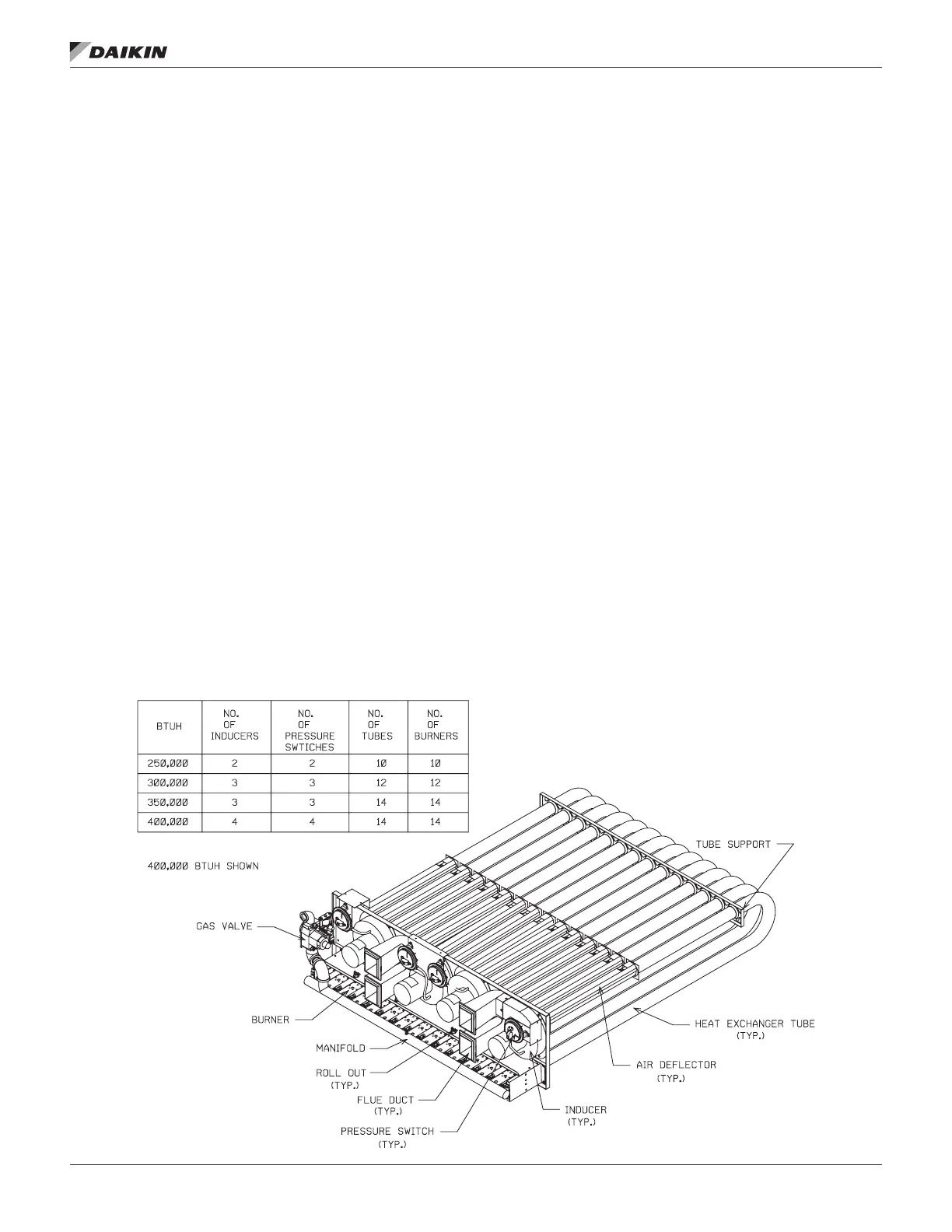
Figure 36: Heat Exchanger Component Identication
 Loading...