IM 972-2 • MAVERICK I ROOFTOP SYSTEMS 6 www.DaikinApplied.com
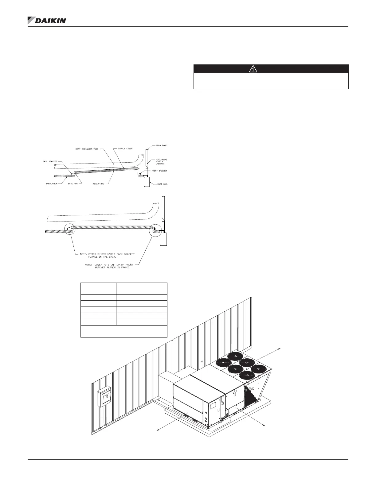
1. Remove the screws and covers from the outside of the
supply and return sections. Also remove and discard the
cover plate.
2. Install the covers over the bottom supply and return
openings, painted side up, inserting the leading ange
under the bracket provided. Place the back ange to top
of the front bracket provided. See Figure 2 and Figure 3.
3. Secure the return and supply cover to front bracket with
two (2) screws.
Figure 2: Horizontal Conversion Detail
Attaching Exhaust and Combustion Air
Inlet Hoods
IMPORTANT
Do not operate this unit without the exhaust/ combustion air inlet hood
properly installed.
The hood ships in a carton in the blower compartment inside
the unit and must be attached when the unit is installed.
To attach exhaust/combustion air inlet hood:
1. Remove screws securing blower access panel and
remove access panel. For location of blower access
panel.
2. Remove exhaust/combustion air inlet hood from the
carton, located inside the blower compartment.
3. Attach blower access panel.
4. Attach the combustion air inlet/exhaust hood with
screws. Screws are in carton with the hood.
5. Vent the unit using the ue exhaust hood, as supplied
from the factory, without alteration or addition. The only
exception is with factory approved additions.
Figure 3: Clearances
Step 2
Step 1
A
B
*D
E
C
VERTICAL
CLEARANCE
+
WITHOUT HORIZONTAL ECONOMIZER/ 42” WITH
HORIZONTAL ECONOMIZER
RECOMMENDED
CLEARANCE
LOCATION
80”
18”
18/42”
18/48”
60”
*WITHOUT ECONOMIZER/48” WITH
ECONOMIZER
A–FRONT
B–CONDENSER COIL
+
C–DUCT SIDE
*D–EVAPORATOR END
E–ABOVE
 Loading...