Si30-408 Method of Troubleshooting
Troubleshooting 89
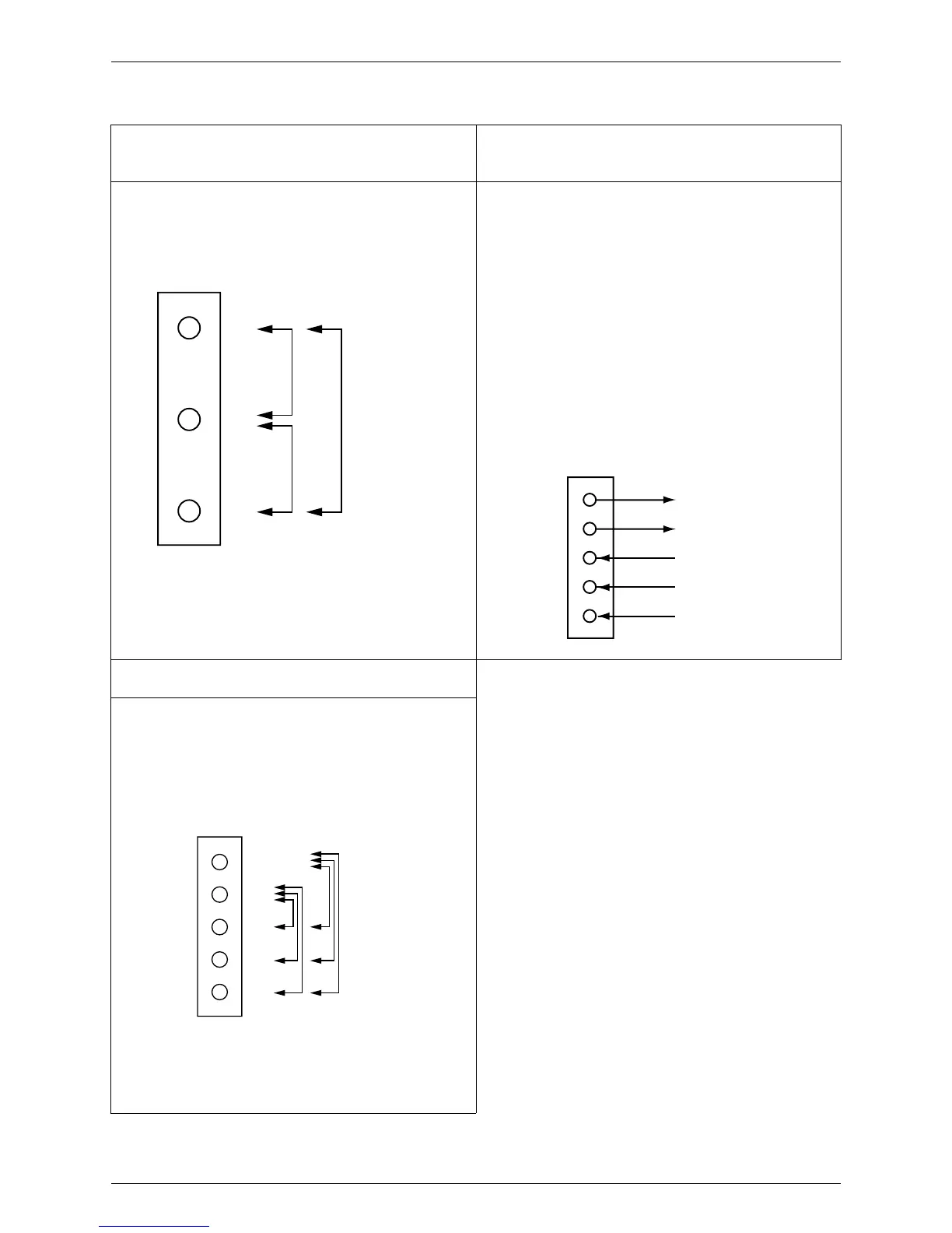
3.7 Check on Outdoor Fan Motor
Check 1
Check on connector of fan motor
(power supply cable)
Check 3
Check on pulse input of fan inverter PC board
position signal
(1) Turn OFF the power supply.
Check on resistance balance and short-circuiting between
phases by measuring each resistance between phases of
U, V, and W with the connector (3-core) at motor side after
disconnect the connector or relay connector.
(1)Disconnect the connector X2A under the conditions of
power supply OFF and operation OFF.
(2) Check that approx. 15 V can be read between pin number
of 4 and 5 in X2A after turn ON the power supply.
(3) Connect the connector X2A under the conditions of power
supply OFF and operation OFF.
(4) Rotate fan motor for one turn manually under the
conditions of power supply ON and operation OFF, and
check on the following items.
Pulses (approx. 0 V and approx. 5 V) can be output for four
times between pin No. 1 and 5 in X2A.
Pulses (approx. 0 V and approx. 5 V) can be output for four
times between pin No. 2 and 5 in X2A.
Pulses (approx. 0 V and approx. 5 V) can be output for four
times between pin No. 3 and 5 in X2A.
Above item (2) cannot be observed.
→
Faulty PC board
→
Replace PC board.
Item (4) cannot be observed.
→
Faulty hall IC
→
Replace
the outdoor fan motor.
Check 2
Check on connector of fan motor (control cable)
(1) Turn OFF the power supply.
(2) Check on resistance balance between terminals (± 20 % or
less) by measuring each resistance between Vcc and U, V,
W, and GND and U, V, W with the connector (5-core) at
motor side after disconnect the connector or relay
connector.
Measuring each resistance
between phases
Red
White
Black
U
V
W
GND
VCC (Approximately 15 V)
Position signal W
Position signal V
Position signal U
5Gray
4 Pink
3 Orange
2 Blue
1 Yellow
GND
VCC
W
V
U
5Gray
4 Pink
3 Orange
2 Blue
1 Yellow
Measure the each
resistance between
Vcc and U, V, W, and
GND and U, V, W.
 Loading...