AK-PC 781A Capacity controller RS8HE202 © Danfoss 2017-07 31
ON/OFF output signals ”DO”
There are two types, as follows:
• Relay outputs
All relay outputs are with change-over
relay so that the required function can be
obtained when the controller is without
voltage.
• Solid state outputs
Reserved for AKV valves, but output can
cut an external relay in and out, as with a
relay output.
The output is only found on the
controller module.
When programming the function must be set:
• Active when the output is activated
• Active when the output is not activated.
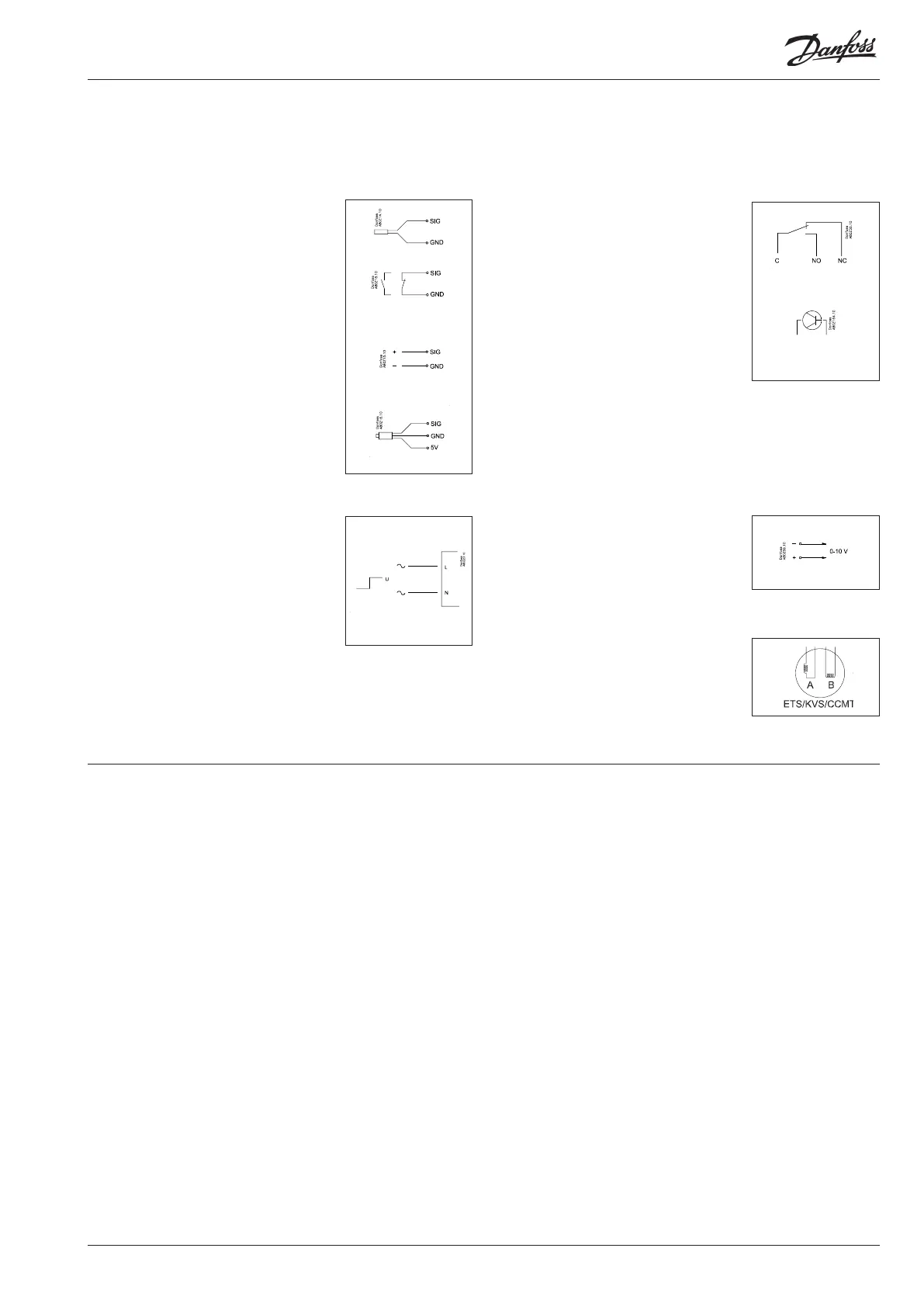
Analog output signal ”AO”
This signal is to be used if a control signal is
to be transmitted to an external unit, e.g. a
frequency converter.
When programming the signal range must
be defined: 0-5 V, 1-5 V, 0-10 V, 2-10 V, 10-0
V or 5-0 V.
Pulse signal for the stepper motors.
This signal is used by valve motors of the
type ETS, KVS and CCMT.
The valve type should be set during pro-
gramming.
Connections
In principle there are the following types of connections:
Analog inputs ”AI”
This signal must be connected to two
terminals.
Signals can be received from the following
sources:
• Temperature signal from Pt 1000 ohm
temperature sensor
• Pulse signal or reset signal
• Contact signal where the input is short-
circuited or ”opened”, respectively
• Voltage signal from 0 to 10 V
• Signal from pressure transmitter AKS 32,
AKS 32R, AKS 2050 or MBS 8250.
The supply voltage is supplied from the
module’s terminal board where there is
both a 5 V supply and a 12 V supply.
When programming the pressure trans-
mitter’s pressure range must be set.
ON/OFF voltage inputs ”DI”
This signal must be connected to two
terminals.
• The signal must have two levels, either 0 V
or ”voltage” on the input.
There are two different extension
modules for this signal type:
- low-voltage signals, e.g. 24 V
- high-voltage signals, e.g. 230 V
When programming the function must be set:
• Active when the input is without voltage
• Active when voltage is applied to the
input.
Limitations
As the system is very flexible regarding the number of connected
units you must check whether your selection complies with the
few limitations there are.
The complexity of the controller is determined by the software,
the size of the processor, and the size of the memory. It provides
the controller with a certain number of connections from which
data can be downloaded, and others where coupling with relays
can be performed.
✔ The sum of connections cannot exceed 120 (AK-PC 781A).
✔ The number of extension modules must be limited so that the
total power in a row will not exceed 32 VA (including control-
ler).
If the AK-CM 102 communication module is used, each row of
AK-CM 102 must not exceed 20 VA (incl. AK-CM 102).
There must not be more than a total of 12 modules (controller
+ 11 modules).
✔ No more than 5 pressure transmitters may be connected to one
controller module.
✔ No more than 5 pressure transmitters may be connected to one
extension module.
Common pressure transmitter
If several controllers receive a signal from the same pressure trans-
mitter, the supply to the affected controllers must be wired so that
it is not possible to switch off one of the controllers without also
switching off the others. (If one controller is switched off, the sig-
nal will be pulled down, and all the other controllers will receive a
signal which is too low)

 Loading...


