46 Capacity controller RS8HE202 © Danfoss 2017-07 AK-PC 781A
Wiring
Decide during planning which function is to be connected and
where this will be.
1. Connect inputs and outputs
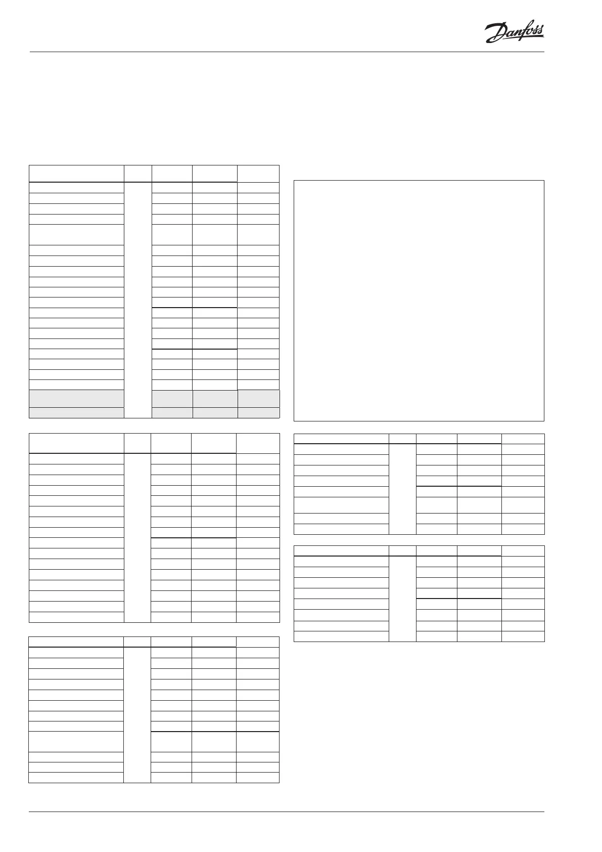
Here are the tables for the example:
Mounting and wiring - continued
The function of the switch functions can be seen in the last column.
There are pressure transmitters AKS 32R and AKS 2050 available for
several pressure ranges.
Here there are two different ones. One up to 59 bar and two up to 159
bar.
Signal Module Point
Terminal
Signal type /
Active at
Level switch, oil, receiver High
2
1 (AI 1) 1 - 2 closed
Level switch, oil, receiver Low 2 (AI 2) 3 - 4 closed
Level switch, oil, Separator 3 (AI 3) 5 - 6 closed
Level switch, CO2 receiver 4 (AI 4) 7 - 8 Open
Pulse reset of stopped compressor 5 (AI 5) 13 - 14 Pulse
6 (AI 6) 15 - 16
Refrigerant, receiver, Prec CO2 7 (AI 7) 17 - 18 AKS 2050-159
Oil receiver, Prec Oil 8 (AI 8) 19 - 20 AKS 2050-159
Compressor 1 9 (DO 1) 25 - 26 - 27 ON
Compressor 2 10 (DO 2) 28 - 29 - 30 ON
Compressor 3 11 (DO 3) 31 - 32 - 33 ON
Compressor 4 12 (DO 4) 34 - 35 - 36 ON
Start /stop of VLT to fans 13 (DO 5) 37 - 38 - 39 ON
3-way valve, tap water, V3tw 14 (DO6) 40 - 41 - 42 ON
3-way valve, heat circuit, V3hr 15 (DO7) 43 - 44 - 45 ON
3-way valve, gas cooler, V3gc 16 (DO8) 46 - 47 - 48 ON
Signal Module Point
Terminal
Signal type /
Active at
Discharge gas temperature - Sd
1
1 (AI 1) 1 - 2 Pt 1000
Suction gas temperature - Ss 2 (AI 2) 3 - 4 Pt 1000
Outdoor temperature - Sc3 3 (AI 3) 5 - 6 Pt 1000
External compressor stop 4 (AI 4) 7 - 8 closed
Thermostat sensor in plant room
- Saux1
5 (AI 5) 9 - 10 Pt 1000
Suction pressure - P0 6 (AI 6) 11 - 12 AKS 2050-59
Condenser pressure - Pc 7 (AI 7) 13 - 14 AKS 2050-159
Level switch, oil, comp. 1 8 (AI 8) 19 - 20 closed
Level switch, oil, comp..2 9 (AI 9) 21 - 22 closed
Level switch, oil, comp..3 10 (AI 10) 23 - 24 closed
Level switch, oil, comp..4 11 (AI 11) 25 - 26 closed
Solenoid valve, oil, Comp. 1 12 (DO 1) 31 - 32 ON
Solenoid valve, oil, Comp. 2 13 (DO 2) 33 - 34 ON
Solenoid valve, oil, Comp. 3 14 (DO 3) 35 - 36 ON
Solenoid valve, oil, Comp. 4 15 (DO 4) 37 - 38 ON
Solenoid valve , oil, Separator 16 (DO 5) 39 - 40 - 41 ON
Circulation pump tw 17 (DO6) 42 - 43 - 44 ON
Circulation pump hr 18 (DO7) 45 - 46 - 47 ON
Room fan 19 (DO8) 48 - 49 - 50 ON
Voltage signal to high pressure
valve, ICMTS
24 - 0-10 V
25 -
Signal Module Point Terminal Active at
Compressor 1 Gen. safety
4
1 (DI 1) 1 - 2 Open
Compressor 2 Gen. safety 2 (DI 2) 3 - 4 Open
Compressor 3 Gen. safety 3 (DI 3) 5 - 6 Open
Compressor 4 Gen. safety 4 (DI 4) 7 - 8 Open
Start/stop heat recovery hr 5 (DI 5) 9 - 10 closed
All comp. common safety 6 (DI 6) 11 - 12 Open
Flow switch FStw 7 (DI 7) 13 - 14 Open
Flow switch FShr 8 (DI 8) 15 - 16 Open
Signal Module Point Terminal Signal type
Temp. gas cooler outlet Sgc
5
1 (AI 1) 1 - 2 Pt 1000
Temp. by-passed gas Shp 2 (AI 2) 3 - 4 Pt 1000
Start/stop heat recovery tw 3 (AI 3) 5 - 6 closed
Gas cooler pressure Pgc 4 (AI 4) 7 - 8 AKS 2050-159
Speed control, compressor 5 (AO 1) 9 - 10 0 - 10 V
Speed control, gas cooler fans 6 (AO 2) 11 - 12 0 - 10 V
Speed control, pump - tw 7 (AO 3) 13 - 14 0 - 10 V
Speed control, pump - hr 8 (AO 4) 15 - 16 0 - 10 V
Signal Module Point/Step Terminal Signal type
Tap water temperature - Stw2
3
1 (AI 1) 1 - 2 Pt 1000
Tap water temperature - Stw3 2 (AI 2) 3 - 4 Pt 1000
Tap water temperature - Stw4 3 (AI 3) 5 - 6 Pt 1000
Tap water temperature - Stw8 4 (AI 4) 7 - 8 Pt 1000
Heat reclaim temperature Shr2 5 (AI 5) 9 - 10 Pt 1000
Heat reclaim temperature Shr3 6 (AI 6) 11 - 12 Pt 1000
Heat reclaim temperature Shr4 7 (AI 7) 13 - 14 Pt 1000
Heat reclaim temperature Shr8 8 (AI 8) 15 - 16 Pt 1000
Stepper signal to by-pass valve,
CCMT
9 (step 1)
25 - 26 - 27 - 28
CCMT (ETS)
10 (step 2) 29 - 30 - 31 - 32
11 (step 3) 33 - 34 - 35 - 36
12 (step 4) 37 - 38 - 39 - 40
Remember the isolation amplifier
If signals are received from different controls, e.g. heat re-
covery for one of the inputs, a galvanically insulated module
should be inserted.

 Loading...


