8 Capacity controller RS8HE202 © Danfoss 2017-07 AK-PC 781A
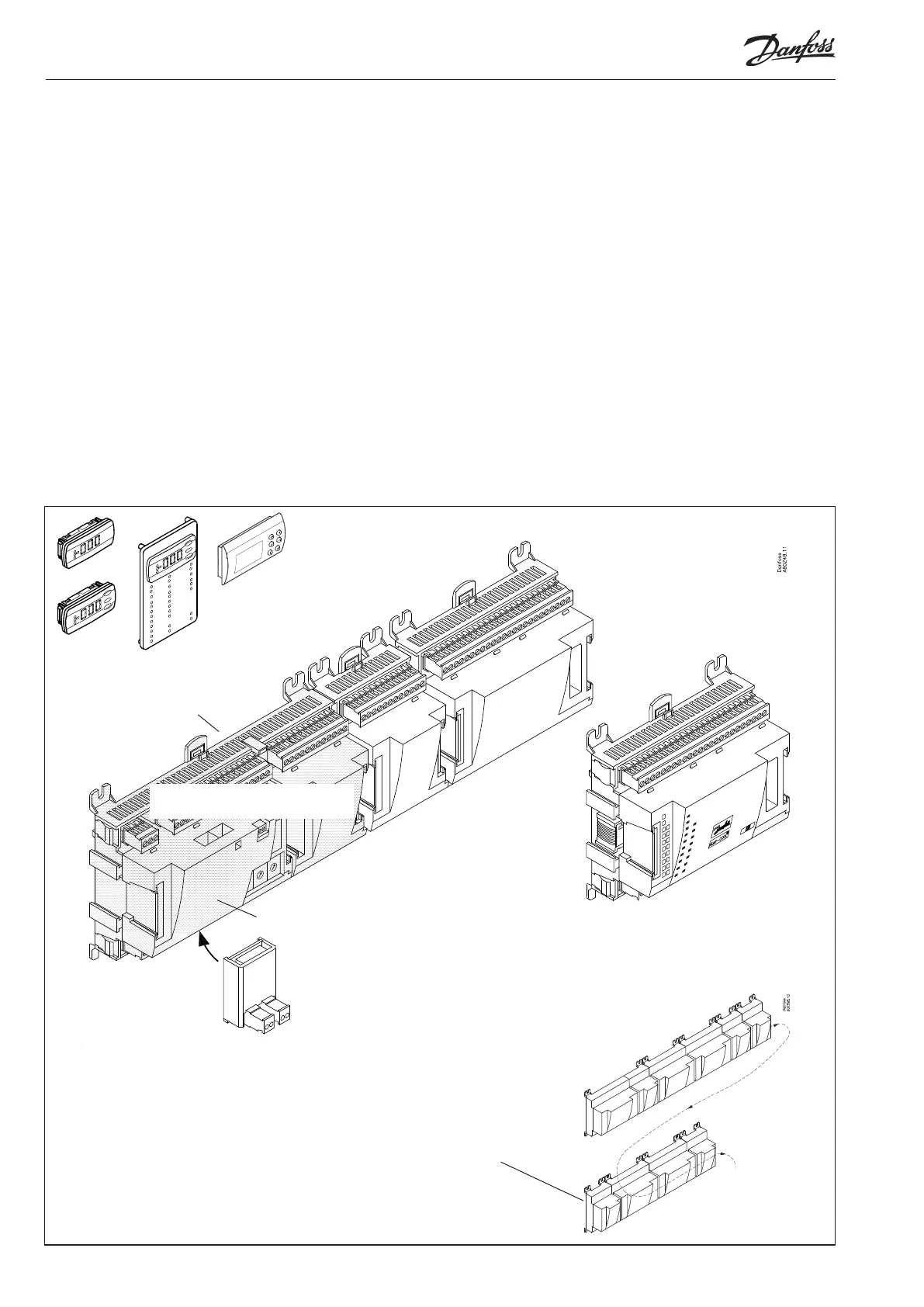
Extension module with ad-
ditional analog inputs
Extension module with additional
relay outputs and additional ana-
log inputs.
The module with additional relay outputs is
also available in a version where the top part
is provided with change-over switches so
that the relays can be overridden.
Extension module with
2x analog output signals
Top part
Controller with analog inputs and
relay outputs.
External display for
suction pressure etc.
Bottom part
Module survey
• Controller module – capable of handling minor plant require-
ments.
• Extension modules. When the complexity becomes greater
and additional inputs or outputs are required, modules can be
attached to the controller. A plug on the side of the module will
transmit the supply voltage and data communication between
the modules.
• Top part
The upper part of the controller module contains the intelli-
gence. This is the unit where the regulation is defined and where
data communication is connected to other controllers in a big-
ger network.
• Connection types
There are various types of inputs and outputs. One type may, for
example, receive signals from sensors and switches, another may
receive a voltage signal, and a third type may be outputs with
relays etc. The individual types are shown in the table below.
• Optional connection
When a regulation is planned (set up) it will generate a need for
a number of connections distributed on the mentioned types.
This connection must then be made on either the controller
module or an extension module. The only thing to be observed
is that the types must not be mixed (an analog input signal must
for instance not be connected to a digital input).
• Programming of connections
The controller must know where you connect the individual
input and output signals. This takes place in a later configura-
tion where each individual connection is defined based on the
following principle:
- to which module
- at which point (”terminals”)
- what is connected (e.g. pressure transmitter/type/
pressure range)
If the row of modules needs to
be interrupted due to length or
external positioning, a communi-
cation module should be used.

 Loading...


