Data
On/off inputs (DI1, DI2)
Input DI1 is used for the printer’s paper function. DI1 is connected to a contact function which is
operated when the paper has been placed in the printer. (Top of form setting).
The DI2 input is used for manual change-over between “default” and “optional” alarm destinations in
connection with the extended alarm routing (cf. section “AKA Alarm Table”).
Light-emitting diodes
- For each communication gate (RS 232/DANBUSS) there are two light-emitting diodes (LED), one
for sending and one for receiving. The diodes are lit, when there is communication to or from the
gateway.
- The status of the ON/OFF inputs and relay-outputs are also indicated with light-emitting diodes.
- There is an LED for power ON
- There is a LED for LON-communication
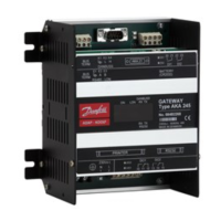
AKA 245
Supply voltage 230 V a.c. -15/+10% 50/60 Hz
Power consumption 4 VA
Relay outputs Max.contact load 1 A / 230 V ohmic
Digital inputs Off -cycle voltage >12 V d.c.
Short-circuit current >15 mA, <50 mA
Changeover level off : < 2 V
Changeover level ON: > 6 V
Ambient temperature During operation 0 to +55°C
During transport -40 to +70°C
Humidity 10 to 90% RH
Enclosure IP 00
Immunity EN 50082-1 Normative requirements
Radiation EN 50081-1 Normative requirements
Protection of data in the event of a
power failure
RAM Backup for approx.1 year
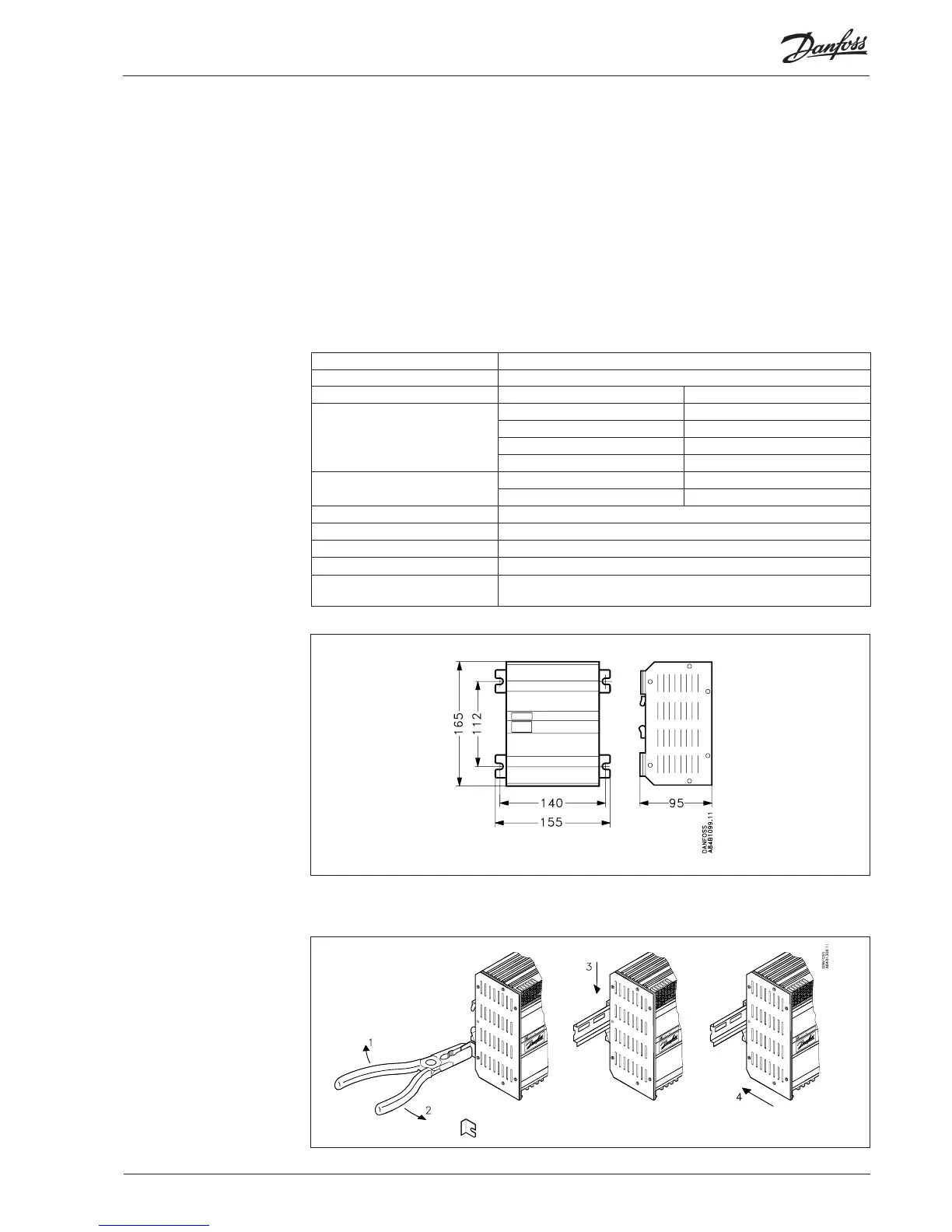
Mounting
The housing can be screwed into place by means of the screw brackets, or it may be mounted on a DIN
rail. When the housing is mounted on a DIN rail, the screw brackets must be broken off .
Dimension
AKA 245 Manual RS8DT102 © Danfoss 09/2004 5
 Loading...