Position Description Position Description
9 Receiver 19 Temperature transmitter
10 Drying filter
Defrosting is initiated by low temperature in the refrigerant circuit after the air exchanger and, among other
things, is dependent on outdoor temperature, humidity and operating time. The length of defrosting varies
depending on the extent of freezing of the air exchanger. Defrost continues until the air heat exchanger is free of
ice and the temperature after the air exchanger has risen to the desired temperature. After completed defrosting
the heat pump returns to the operating mode before defrosting.
During defrosting the heat pump retrieves energy from the house's heating system. The water volume in the heat-
ing system can be increased by installing a buffer tank. The buffer tank can also act as a surge tank.
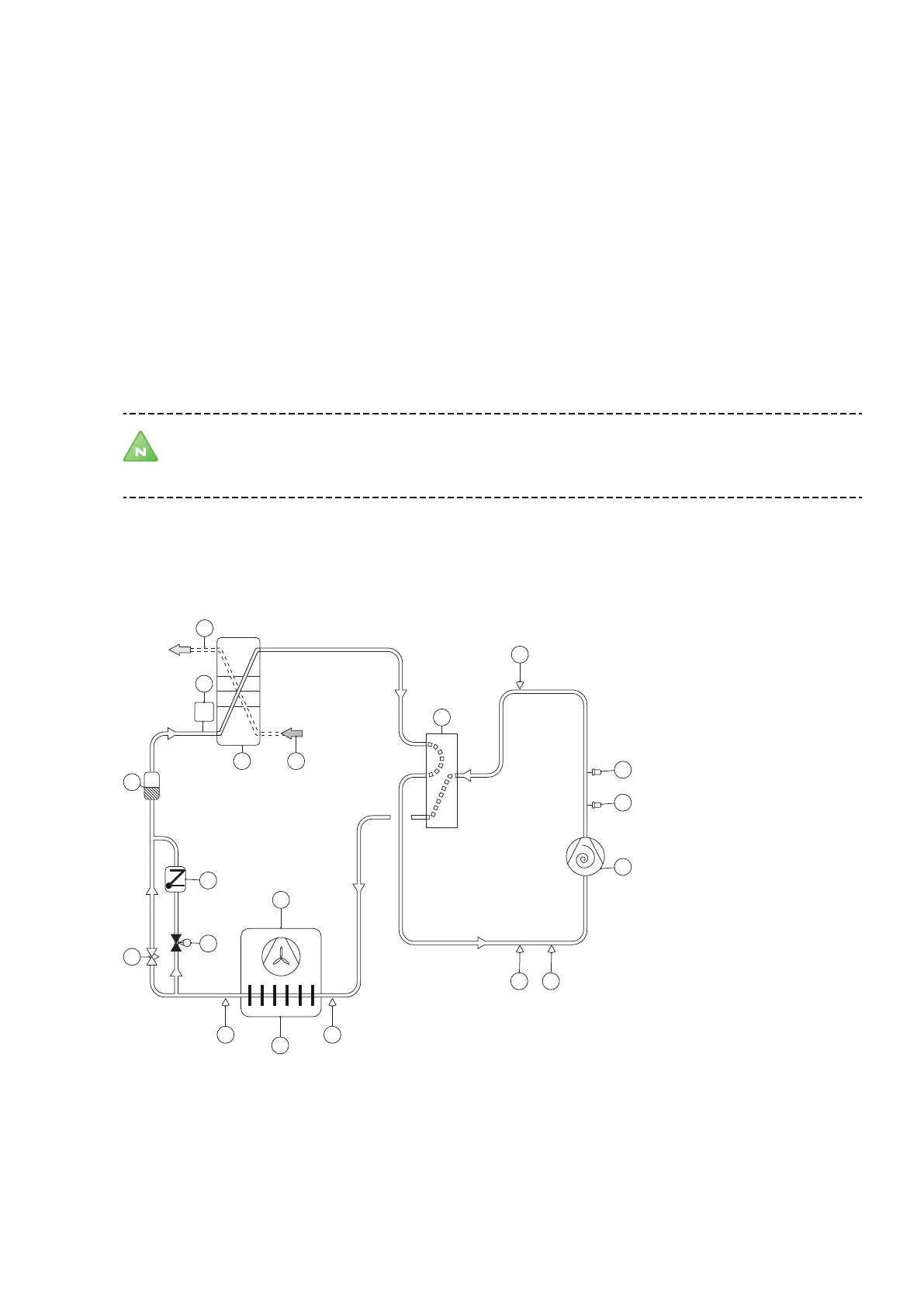
4.7 Cooling function
The heat pump produces cooling (see figure below).
The refrigerant process is similar to that at the defrosting function.
Note! The designations for condenser and evaporator are switched during the cooling function (like the
defrosting function) compared to the heating function, because the designations follow the cooling
technical function that respective units have (evaporation respectively condensing).
When the compressor (1) receives a start signal the refrigerant is compressed in gas form via the 4 way valve (5) to
the air exchanger (15). The hot refrigerant gives off heat to the air exchanger (15), shifts to liquid phase and contin-
ues to the plate heat exchanger (7). In the plate heat exchanger (7) the refrigerant is heated to gas form by the
hotter heating system (6). The heating system is cooled. The refrigerant continues via the 4 way valve (5) back to
the compressor (1).
3
2
1
1918
17
15
14
16
11
13
12
10
9
8
7 6
5
4
Position Description Position Description
1 Compressor 11 Electronic expansion valve
2 Operating pressure switch 12 Non-return valve
3 High pressure switch 13 Solenoid
20 – Installation instructions VMGFD102
 Loading...