9 Information menu
9.1
Menu overview
•
OPERAT.
•
HEATING
•
DISTRIBUTION CIRCUIT1
•
DISTRIBUTION CIRCUIT2
•
HOT WATER
•
COOLING
•
POOL
•
BUFFER TANK
•
OP. DATA
•
OPERAT. TIME
•
DEFROST
•
CALENDAR
o
CLOCK
o
HOT WATER
o
EVU
o
SILENT MODE
o
TEMP.REDUCTION
o
CONCRETE DRYING PROG.
•
ALARM
•
LANGUAGE
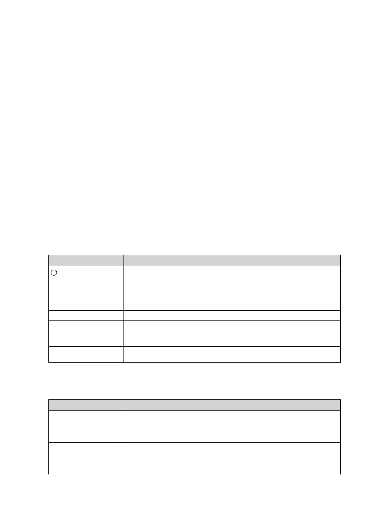
9.2 OPERAT.
Parameter Meaning
(OFF)
The installation is fully switched off. This mode is also used to acknowledge certain alarms.
To select OFF as operating mode, press the minus sign once to scroll down one step and
press the right arrow once. Press CANCEL to return to the starting point without changing.
AUTO Automatic operation with both heat pump and auxiliary heater permitted. If the number of
power stages for auxiliary heating are set to zero (SERVICE -> AUX. HEATER -> MAX STEP)
only AUTO or COMPRESSOR can be selected as operating mode.
COMPRESSOR Operation with only compressor permitted.
AUX. HEATER Operation with only auxiliary heater permitted.
HOT WATER Operation with heat pump for hot water production and auxiliary heater during peak heat-
ing charging (anti-legionella function).
MANUAL TEST Only displayed when the value for MANUAL TEST is set to 2 in
The SERVICE menu. Outputs that control components are activated manually.
9.3 HEATING
Parameter Meaning
CURVE Calculated supply temperature at 0°C outdoor temperature. Shown as a graphic curve. The
curve will be limited by the set values of MIN and MAX.
Factory setting: 40°C (for under floor heating 30°C), range: 22°C – 56°C
MIN Minimum permitted supply temperature, if the temperature for heat stop has been reached
and the heat pump has stopped.
Factory setting: 10°C, range: 10°C – 50°C
Installation instructions VMGFD102 – 47
 Loading...