DKRCI.PD.RP0.A4.02 | 6
Setup & service menu - COMMISSIONING
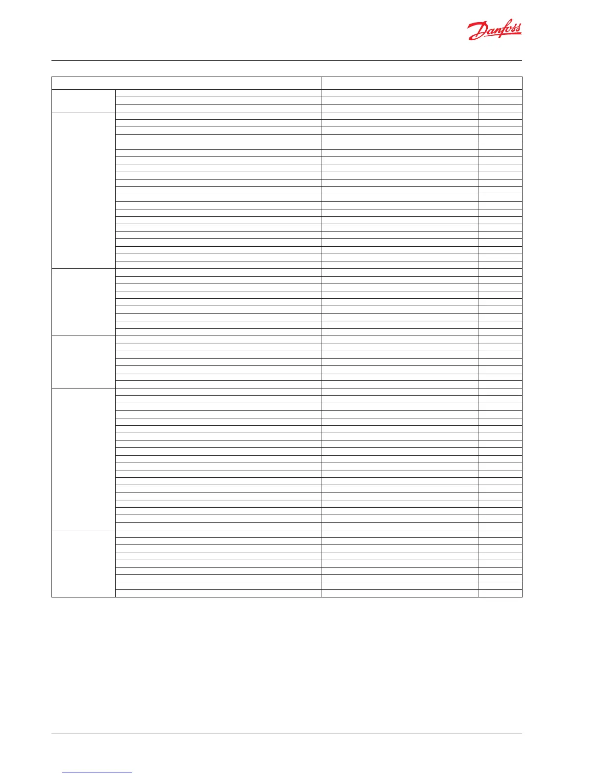
Parameter Options
Default
values
Reference Main switch On, O O
Liquid level setpoint 0 - 100% 50.0%
Operation mode Master, IO, Slave Master
Alarm setup Lower level limit 0 - 100% 15%
Upper level limit 0 - 100% 85%
Level alarm mode Time, Hysteresis Time
Lower delay 0 - 999 sec 10 sec
Upper delay 0 - 999 sec 50 sec
Lower level hysteresis 0-20 % 3%
Upper level hysteresis 0-20 % 5%
Function common alarm Not follow; Follow up; Follow low; Follow all Not follow
Oscillation detect band 0 - 100% 100%
Oscillation detect timeout 2 - 30 min 20 min
Force pump OFF in stop mode Yes / No No
IO Lower level limit 0 - 100% 5%
IO Upper level limit 0 - 100% 95%
IO Lower level hysteresis 0-20 % 3%
IO Upper level hysteresis 0-20 % 3%
IO Lower delay 0 - 999 sec 10 sec
IO Upper delay 0 - 999 sec 50 sec
IO Level limit 0 - 100% 50%
IO Level delay 0 - 999 sec 10 sec
IO Level hysteresis 0-20 % 3%
IO Level action Falling,Rising Falling
Control Control Method On/O ,P, PI PI
Regulating principle Low, High Low
P-band 5 - 200% 30.0%
Integration time Tn 60 - 600 sec 400 sec
Neutral zone 0 - 25% 2.0%
Dierence 0,5-25% 2%
Period time for AKV/AKVA 3-15 sec 6 sec
Minimum OD 0 - 99% 0%
Maximum OD 1 - 100% 100%
Display Language EN,CN,PT,RU,SP,FR,IT, GER, ARAB EN
Output indication level, OD Level
Login timeout 1 - 120 min 10 min
Backlight timeout 0 - 120 min 2 min
Password daily 3 -digit, 0 - 999 100
Password service 3 -digit, 0 - 999 200
Password commission 3 -digit, 0 - 999 300
IO cong System conguration ICAD+NC, ICAD, AKV/A+NC, AKV/A, NC only ICAD + NC
Level signal setup AKS 4100, AKS 41, Current, Voltage AKS4100
Voltage at low liquid level 0-10V 0 V
Voltage at high liquid level 0 -10V 10 V
Current at low liquid level 0-20 mA 4 mA
Current at high liquid level 0-20 mA 20 mA
Valve position setup Not used, Current, Voltage Not used
Voltage at closed valve position 0-10V 0 V
Voltage at open valve position 0-10V 10 V
Current at closed valve position 0-20 mA 4 mA
Current at open valve position 0-20 mA 20 mA
Common alarm setup D04, High alarm, D03, Disp only High alarm
Multiple valve setup Not used, 2 same cap, 2 dif cap, 3 same cap, 3 dif cap Not used
Multiple valve pattern Parallel,Sequence Parallel
Valve A capacity 0-100 % 50%
Valve B capacity 0-100 % 50%
Valve C capacity 0-100 % 30%
ICAD takeover OD 0-100% 80%
IO module setup Used, Not used Not used
Communication CAN ID 1 - 127 1
CAN baudrate 20k, 50k, 125k, 250k, 500k, 1M 500k
Modbus ID 0 - 120 1
Modbus baudrate 0, 1200, 2400, 4800, 9600, 14400, 19200, 28800, 38400 19200
Modbus mode 8N1, 8E1, 8N2 8E1
Modbus mapping Operation, Setup Operation
Valve B CAN ID 1 - 127 2
Valve C CAN ID 1 - 127 3
IO Mod. CAN ID 1 - 127 4
To be continued......

 Loading...