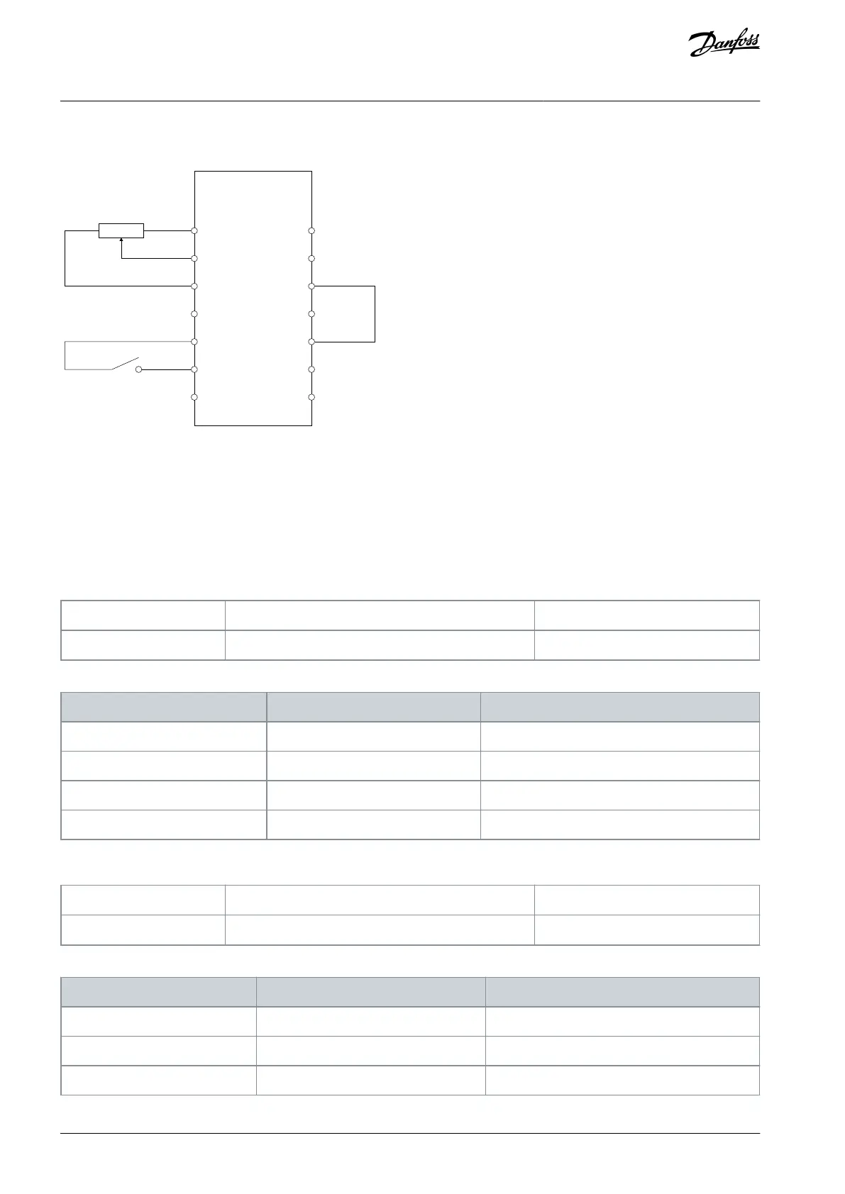
7.5 Setup and Connection Examples for General Purpose I/O
1 (+10V)
Reference:
Potentiometer
Start
Forward
X14
3 (AI2)
5 (GND)
7 (DO1)
9 (24V)
11 (DI1)
13 (DI3)
2 (AI1)
e30bk552.10
4 (AO)
6 (GND)
8 (DO2)
10 (DGND)
12 (DI2)
14 (DGND)
Illustration 31: Wiring Configuration for General Purpose I/O Option OC7C0, Terminal X14
The digital input is isolated from the analog signal. If used with common ground, the connection is made between GND and DGND.
7.6 Parameter Descriptions for General Purpose I/O
7.6.1 I/O Status (Menu Index 9.3)
P 9.3.1 Digital Input Status
Description: Shows the digital input I/O word. Each bit represents the status of a digital input.
Parameter Type: Range (0 — 65535)
Table 34: Bit Descriptions for Digital Input
P 9.3.2 Digital Output Status
Description: Shows the digital output I/O word. Each bit represents the status of a digital output.
Parameter Type: Range (0 — 65535)
Table 35: Bit Descriptions for Digital Output
AQ390830267692en-000601 / 136R027352 | Danfoss A/S © 2023.06
General Purpose I/O Installation
and Configuration
Functional Extension Options
Operating Guide
 Loading...


