•
•
•
•
•
•
-
4 Installation
4.1 Verifying the Shipment and Contents
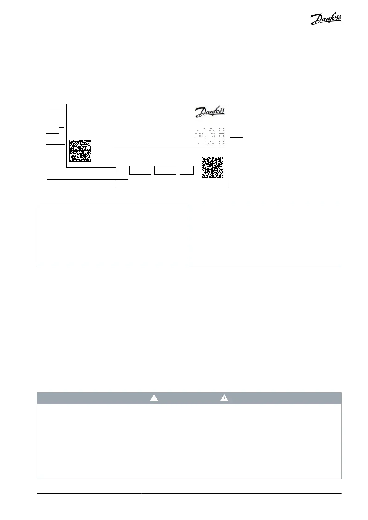
Make sure that the items supplied and the information on the product label correspond to the order confirmation. The product
label is placed on the front and right side of the option casing.
P/N: 136B0160
S/N: 123456G123
2312
P/N: 136B0160
S/N: 123456G123 - 2312 / DG
250 VAC 2A (AC-1) / 24 VDC 2 A (DC-1)
Ord. No: 136B1567
2 3 5 6
6
Illustration 2: Example of a Product Label
Product name of the functional extension
Code number identifying the option
2D code containing code number, serial number,
production year and week, and product name.
Identification of I/O connections on the option
Order number identifying the option kit that was or-
dered
Compliance and approval markings (if not covered
by drive approvals).
4.2 Items Supplied
Functional extension options can be ordered as a preinstalled option by using the dedicated model code, or as a separate option for
field mounting by using the code number.
When the option is not mounted at the factory, the following items are included in the shipment:
Option board + connector(s)
EMC plate
Screw
Option connector
Metal clamp
Installation guide
4.3 Installing Functional Extensions in Frequency Converters
The instructions in this chapter apply to frequency converters with an integrated control board.
D A N G E R
SHOCK HAZARD FROM THE AC DRIVE
Touching electrical parts of the drive can cause death or serious injury even after the equipment has been disconnected from AC
power.
Perform the following steps before touching any internal components:
Disconnect the mains power.
Disconnect the motor.
Disconnect external connections to the DC terminals of the drive.
Wait for the capacitors to discharge fully. Refer to the label on the drive for the correct discharge time.
Ensure that the DC-link capacitors have discharged fully by measuring the DC link with a voltage meter.
AQ390830267692en-000601 / 136R0273 | 9Danfoss A/S © 2023.06
Installation
Functional Extension Options
Operating Guide