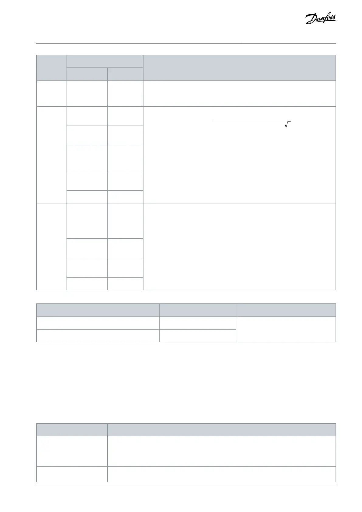
Maxexcitationvoltage
rms
=
7V
Resolvertransformationratiox 2
Encoder
simulation
(TTL Out-
put)
Minimum:
1.5 V
Typical: 2 V
differential
Table 7: Cable Specifications for Encoder/Resolver Option OC7M0
Cross-section [mm
2
(AWG)]
Minimum stripping length [mm (in)]
Flexible/rigid wire without cable end sleeves
Flexible wire with cable end sleeves with collar
A standard RS485 interface supports cable lengths up to 1200 m (3940 ft) depending on signal frequency and cable type. Consult
the documentation for the respective encoder or resolver for details on allowed cable length.
5.5 Setup and Connection Examples for Encoder/Resolver OC7M0
5.5.1 Incremental Encoder
With TTL and HTL incremental encoder, the actual position is 0 after power-up, and encoder pulses are counted to increment or
decrement the actual position. For improved resolution with TTL and HTL encoders, both the positive and negative edge of A and B
pulses are detected giving 4 quad counts per encoder pulse.
Table 8: Parameters for Incremental Encoder
9.4.1 Interface configuration
Select according to the type of connected encoder:
[1] 2 track Incremental A, B.
[3] 3 track Incremental A, B, Z.
9.4.4 Encoder Supply Voltage
Set the appropriate supply voltage.
AQ390830267692en-000601 / 136R0273 | 17Danfoss A/S © 2023.06
Encoder/Resolver Installation and
Configuration
Functional Extension Options
Operating Guide
 Loading...


