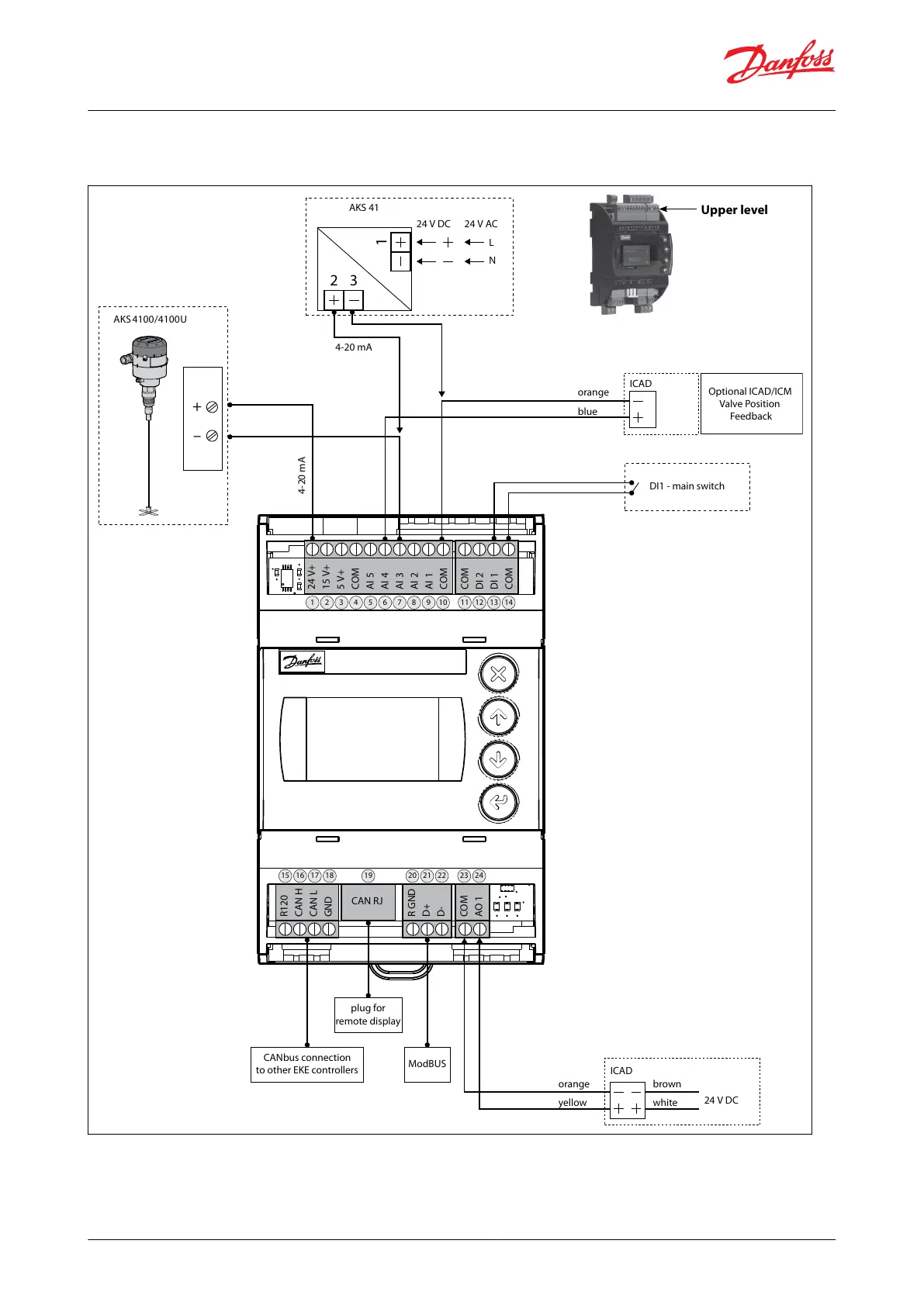
Wiring diagram showing ICAD wired to a Danfoss EKE controller
Figure 11: ICAD wired to a Danfoss EKE controller
AKS 4100/4100U
AKS 41
DI1 - main switch
4-20 mA
CANbus connection
to other EKE controllers
plug for
remote display
ModBUS
4-20 mA
24 V DC
orange
Optional ICAD/ICM
Valve Position
Feedback
ICAD
blue
24 V AC
L
N
+
–
1
2 3
orange
ICAD
yellow
brown
white
24 V+
15 V+
5 V+
COM
AI 5
AI 4
AI 3
AI 2
AI 1
COM
COM
DI 2
DI 1
COM
R120
CAN H
CAN L
GND
R GND
D+
D-
COM
AO 1
CAN RJ
24 V DC
1
15 16 17 18 19 20 21 22 23 24
2 3 4 5 6 7 8 9 10 11 12 13 14
Upper level
NOTE:
For instructions on completely wiring an EKE controller, please see the relevant EKE controller manual.
© Danfoss | Climate Solutions | 2024.01 BC465027827472en-000102 | 13
ICM and ICMTS Motorized Valves with ICAD Actuators
 Loading...