In order to avoid potential equalizing currents in the
shield, the cable shield can be grounded via terminal
61, which is connected to the frame via an RC link.
Bus termination
The bus must be terminated by a resistor network at
both ends. For this purpose, set switches 2 and 3 on
the control card for "ON".
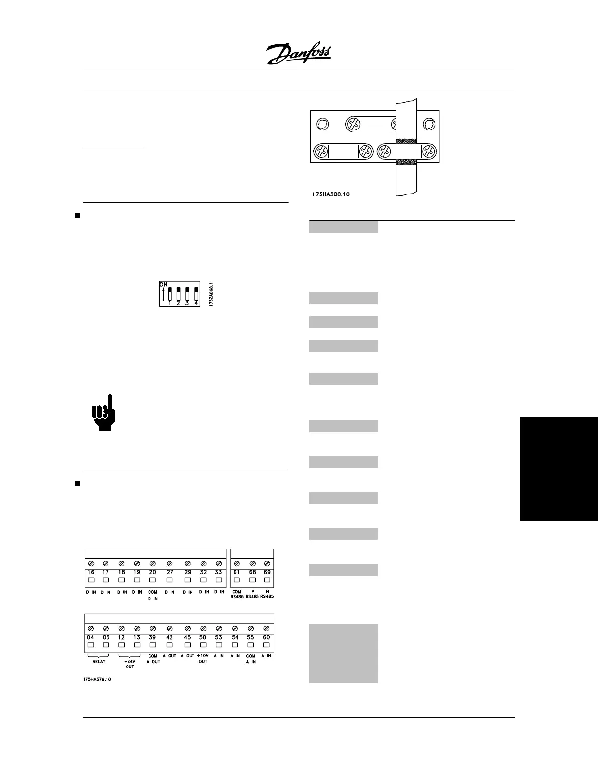
DIP Switches 1-4
The dipswitch is located on the control card.
It is used for serial communication, terminals 68 and
69.
The switching position shown is the factory setting.
Switch 1 has no function.
Switches 2 and 3 are used for terminating an RS-485
interface, serial communication.
Switch 4 is used for separating the common potential
for the internal 24 V DC supply from the common po-
tential of the external 24 V DC supply.
NOTE
Please note that when switch 4 is in the
"OFF" position, the external 24 V DC sup-
ply is galvanically isolated from the ad-
justable frequency drive.
Installation of control cables
Tightening-up torque: 0.5-0.6 Nm
Screw size: M3
See section earthing of braided screened/armoured
control cables.
No. Function
12, 13 Voltage supply to digital inputs For
the 24 V DC to be usable for the
digital inputs, switch 4 on the con-
trol card must be closed. position
"ON".
16-33 Digital inputs/encoder inputs
20 Ground for digital inputs
39 Ground for analogue/digital outputs
42, 45 Analogue/digital outputs for indicat-
ing frequency, reference, current
and torque
50 Supply voltage to potentiometer
and thermistor 10 V DC
53, 54 Analogue reference input, voltage
0 - ±10 V
55 Ground for analogue reference in-
puts
60 Analogue reference input, current
0/4-20 mA
61 Termination for serial communica-
tion. See section Bus connection.
This terminal is normally not to be
used.
68, 69
RS 485 interface, serial communi-
cation. Where the VLT frequency
converter is connected to a bus,
switches 2 and 3 (switches 1- 4)
must be closed on the first and the
VLT
®
5000 Series
MG.51.C5.22 - VLT
p
is a registered Danfoss trademark. 65
Installation
 Loading...


