VLT
®
8000 AQUA
■ Inputs and outputs 300-328
In this parameter group, the
functions that relate to the
input and output terminals
of the frequency converter
are defined. The digital
inputs (terminals 16, 17, 18,
19, 27, 29, 32 and 33) are
programmed in parameters
300-307.
The table below gives the options for programming
the inputs. The digital inputs require a signal of 0 or
24 V DC. A signal lower than 5 V DC is a logic ‘0’,
while a signal higher than 10 V DC is a logic ‘1’.
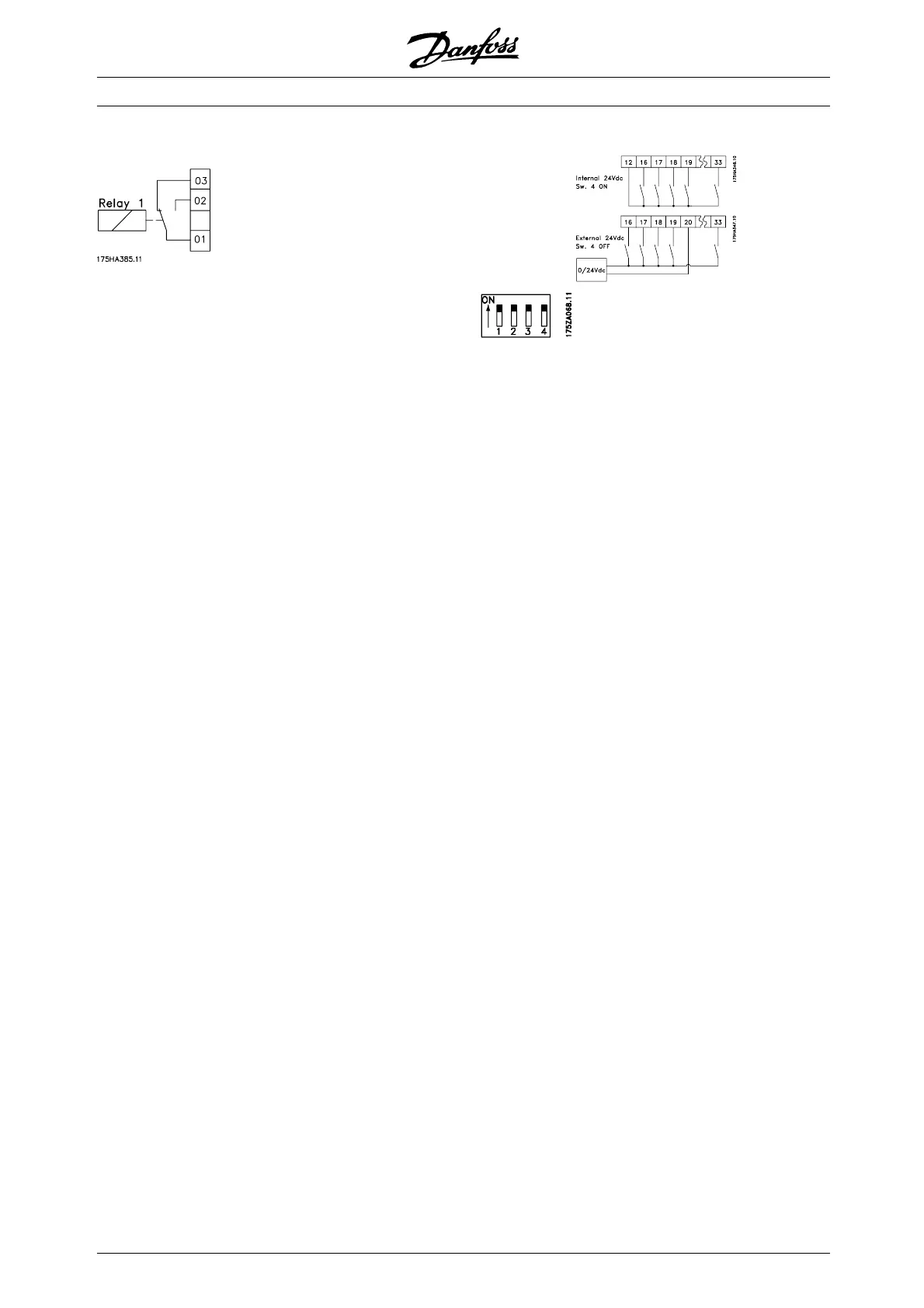
The terminals for the digital inputs can be
connected to the internal 24 V DC supply, or an
external 24 V DC supply can be connected.
The drawings in the next column show one Setup
using the internal 24 V DC supply and one Setup
using an external 24 V DC supply.
Switch 4, which is
located on the Dip
switch control card,
is used for separating the common potential of the
internal 24 V DC supply from the common potential
of the external 24 V DC supply. See Electrical
installation.
Please note that when Switch 4 is in the OFF
position, the external 24 V DC supply is galvanically
isolated from the frequency converter.
✭ = factory setting. () = display text [] = value for use in communication via serial communication port
MG.83.A2.02 - VLT is a registered Danfoss trademark
118
 Loading...


