8.5.14 Input Terminal Signal Tests
The presence of signals on either the digital or analog
input terminals of the drive can be veried on the drive
display. Parameter 16-60 Digital Input –
parameter 16-64 Analog Input 54 show the status for the
standard inputs. Other parameters show the status of
option inputs.
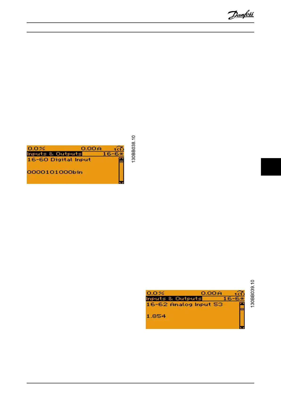
Digital inputs
View the digital inputs by using parameter 16-60 Digital
Input. The status of control terminals 18, 19, 27, 29, 32, and
33 are shown (left to right) with terminal 33 on the right
of the display. A 1 indicates the presence of a signal, which
means the logic is true and the input is on.
Illustration 8.18 Digital Inputs Display
If the display does not show the correct signal, investigate
the following:
•
External control wiring to the drive
•
Incorrect programming of parameter 5-00 Digital
I/O Mode
•
Faulty control card
Use parameter 5-00 Digital I/O Mode to program the digital
inputs to either accept a sourcing output (PNP) or a
sinking output (NPN). When programmed for PNP (factory
default), the digital input turns on when 24 V DC is applied
to the digital input terminal. When programmed for NPN,
the digital input turns on when the terminal is connected
to signal common (terminal 20).
The power for the digital inputs can either come from the
(+) 24 V DC built into the drive, or from an external supply.
If an external supply is used, reference the common of the
supply to terminal 20.
Check for an internal power supply
1. Connect the (-) negative meter lead to
terminal 20.
2. Connect the (+) positive meter lead to
terminal 12 or terminal 13 and measure the DC
voltage.
A correct reading is 21–27 V DC. If the supply voltage is
not present, perform the basic control card voltage test.
See chapter 8.5.3 Basic Control Card Voltage Test.
Check the individual inputs if parameter 5-00 Digital I/O
Mode is PNP
1. Connect the (-) negative meter lead to
terminal 20.
2. Connect the (+) positive meter lead to each
digital input in sequence and measure the DC
voltage.
The correct display for each digital input where the voltage
reading is greater than 10 V DC is 1. The correct display for
each digital input where the voltage reading is less than 5
V DC is 0. If the display does not correspond with the
measured inputs, the digital inputs on the control card
have failed. Replace the control card.
Check the individual inputs if parameter 5-00 Digital I/O
Mode is NPN
1. Connect the (-) negative meter lead to
terminal 20.
2. Connect the (+) positive meter lead to each
digital input in sequence and measure the DC
voltage.
The correct display for each digital input where the voltage
reading is less than 14 V DC is 1. The correct display for
each digital input where the voltage reading is greater
than 19 V DC is 0. If the display does not correspond with
the measured inputs, the digital inputs on the control card
have failed. Replace the control card.
Analog inputs
Terminals 53 and 54 are the standard analog input
terminals. Each terminal can be
congured as a voltage
input or a current input. Switch S201 on the control card
congures terminal 53. Switch S202 congures terminal 54.
Use parameter 16-62 Analog Input 53 to show the value on
terminal 53 and parameter 16-64 Analog Input 54 to show
the value on terminal 54.
Illustration 8.19 Analog Inputs Display
Test Procedures Service Guide
MG94A502 Danfoss A/S © 02/2019 All rights reserved. 117
8 8
 Loading...


