4 Operator Interface and Drive Control
4.1 Introduction
Drives are designed with self-diagnostic circuitry to isolate
fault conditions and show messages that simplify trouble-
shooting and service. The operating status of the drive is
shown in real time. Virtually every command given to the
drive results in some indication on the local control panel
(LCP) display. Fault logs are maintained within the drive for
fault history.
The drive monitors supply and output voltages along with
the operational condition of the motor and load. When the
drive issues a warning or alarm, the fault is not always
within the drive itself. In fact, for most service calls, the
fault condition exists outside of the drive. Most of the
warnings and alarms that the drive shows are in response
to faults outside of the drive. This service guide provides
techniques and test procedures to help isolate a fault
condition whether in the drive or elsewhere.
Familiarity with the information provided on the LCP
display is important. More diagnostic data can be accessed
easily through the LCP.
4.2
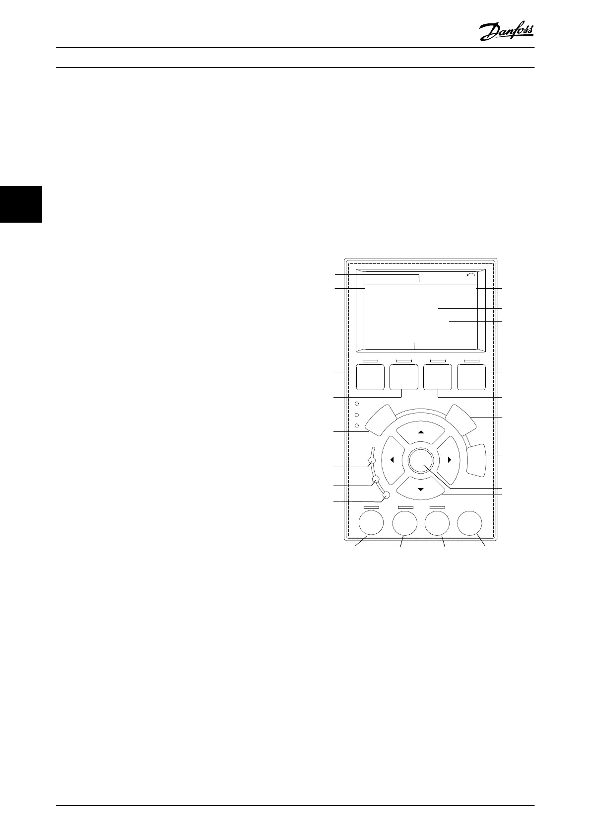
Local Control Panel
The local control panel (LCP) is the combined display and
keypad on the front of the unit. See Illustration 4.1.
The LCP has several user functions:
•
Starts, stops, and controls speed when in local
control.
•
Shows operational data, status, warnings, and
alarms.
•
Programs drive functions.
•
Manually resets the drive after a fault when auto
reset is inactive.
4.2.1 Layout
The LCP is activated when the drive receives power from 1
of the following:
•
Mains voltage
•
DC bus terminal
•
24 V DC external supply
The LCP is divided into the following functional groups:
130BD809.11
Auto
On
Reset
Hand
On
Off
Status
Quick
Menu
Main
Menu
Alarm
Log
Back
Cancel
Info
OK
Status
1(1)
0.00 kW
Off Remote Stop
0.0Hz
On
Alarm
Warn.
0.00 A
0.0 %
2605 kWh
A1.1
A1.2
A1.3
A2
A3
B1
B2
B4
B3
C1
C2
C3
C4
C5
D1
D2
D3
E1 E2 E3 E4
Illustration 4.1 Local Control Panel (LCP)
Operator Interface and Driv...
VLT
®
FC Series, D1h–D8h, Da2/Db2/Da4/Db4, E1h–E4h, J8/J9
30 Danfoss A/S © 02/2019 All rights reserved. MG94A502
44
 Loading...


