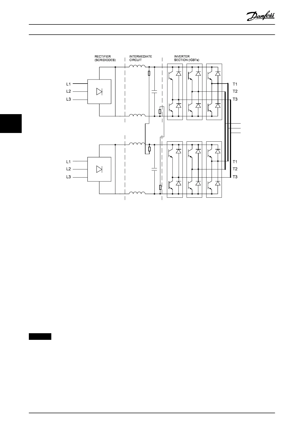
Illustration 5.4 Typical Power Section of a 2-module Parallel System
5.3
Sequence of Operation
5.3.1 Rectier Section
When power is rst applied to the drive, it enters through
the input terminals (L1, L2, and L3). Then, power moves to
the disconnect and/or RFI
lter option, depending on the
conguration. If equipped with optional fuses, these fuses
limit damage caused by a short circuit in the power
section. The input power is also connected to the inrush
circuit. This circuit supplies gate signals to the SCRs, with a
high ring angle (near 180°) at rst. The ring angle
decreases with every successive AC cycle until it reaches 0°.
This process increases the DC voltage slowly over a period
of several line cycles, thus greatly reducing the current for
charging the DC capacitors.
NOTICE
In parallel drive systems, the input power is applied to
each module.
The low voltage supplies are activated when the DC bus
reaches approximately 50 V DC less than the alarm voltage
low for the DC bus. See chapter 14 Product Specications.
After a short delay, an inrush enable signal is sent from the
control card to the inrush card SCR gating circuit. The SCRs
are automatically gated when forward biased, acting
similar to an uncontrolled rectier as a result.
When the DC bus capacitors are fully charged, the voltage
on the DC bus equals the peak voltage of the input AC
line. Theoretically, this gure can be calculated by
multiplying the AC line value by 1.414 (V AC x 1.414).
However, since AC ripple voltage is present on the DC bus,
the actual DC value is closer to V AC x 1.38 under
unloaded conditions. It can drop to V AC x 1.32 while
running under load. For example, a drive connected to a
nominal 460 V line, while sitting idle, the DC bus voltage is
approximately 635 V DC (460 x 1.38).
As long as power is applied to the drive, this voltage is
present in the DC-link and inverter circuits. It is also fed to
the switch mode power supply on the power card and is
used for generating all other low voltage supplies.
Internal Drive Operation
VLT
®
FC Series, D1h–D8h, Da2/Db2/Da4/Db4, E1h–E4h, J8/J9
46 Danfoss A/S © 02/2019 All rights reserved. MG94A502
55
 Loading...


