11.3 D7h/D8h Disassembly and Assembly
The D7h and D8h drives are D2h drives with extended
options cabinets. The unit proled here includes a
contactor, disconnect, and brake option, and is 690 V
power range. Some procedures apply to all congurations,
but some vary depending on the size of the drive,
extended options cabinet, and selected options.
11.3.1 Removing the Drive from the
Extended Options Cabinet
To remove the drive from the extended options cabinet,
use the following steps. Refer to Illustration 11.37.
NOTICE
DRIVE WEIGHT
The D8h drive is heavy. To avoid injury, remove it from
the extended options cabinet using 2 people or
appropriate equipment for lifting.
NOTICE
FASTENER REMOVAL
When removing the fasteners from the top ange,
remove only the center 2 fasteners, which hold the drive
and extended options cabinet together. The outer
fasteners continue to support the extended options
cabinet after the drive has been removed.
Disassembly
1. Remove the input, output, and brake (if present)
busbars in accordance with
chapter 11.3.2 Accessing the Heat Sink Fan in
D7h/D8h Drives.
2. Remove the ground bracket by removing 2 nuts
(17 mm) from the ground studs on the left side
of the plate, 1 screw (T25) from the center, and 2
nuts (8 mm) from the bottom.
3. Remove 6 nuts (8 mm) inside the option cabinet
on the bottom of the 3 brackets between the
option cabinet and the main enclosure.
4. Remove 2 connector plates on the top of the
drive by removing 8 screws (T25), 4 from each
plate.
5. Lift the drive away from the extended options
cabinet.
Reassembly
Reinstall in reverse order of this procedure. Tighten
hardware according to chapter 14.1 Fastener Torque Ratings.
11.3.2 Accessing the Heat Sink Fan in
D7h/D8h Drives
Disassembly
The D7h and D8h drives include an extended options
cabinet mounted below the main enclosure. To access the
heat sink fan in D7h/D8h drives, remove the busbars
between the main enclosure and the extended options
cabinet using the following steps. In drives with dierent
option congurations, the busbars can vary slightly from
the busbars pictured.
1. Remove the air bae covering the interior
components.
2. Remove the EMC shield by removing 2 screws
(T25).
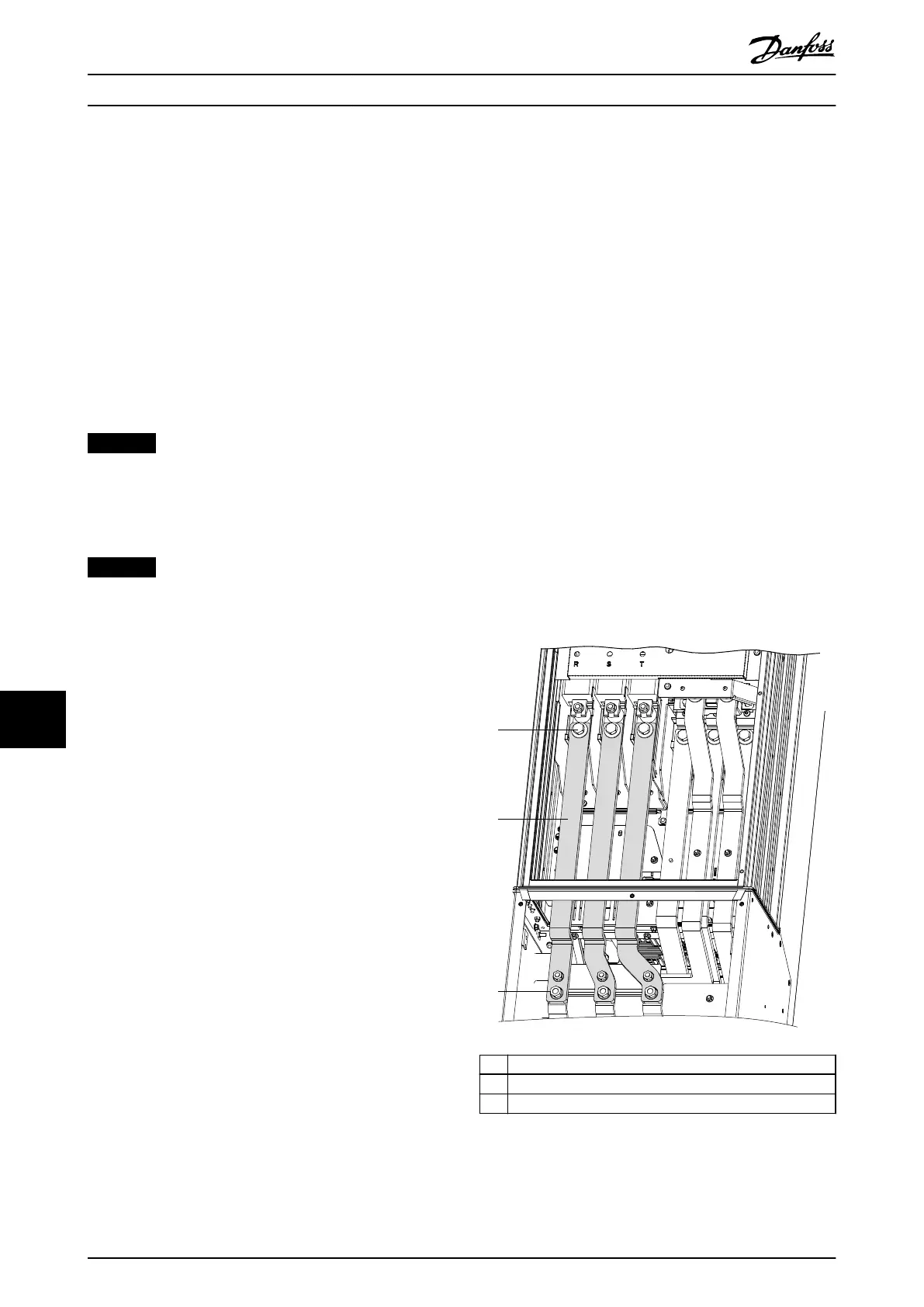
3. Remove the 3 mains input jumper busbars
between the main enclosure and the extended
options cabinet. See Illustration 11.37:
3a Remove 3 screws (17 mm) from the top
of the mains input jumper busbars, 1
per busbar.
3b Remove 3 nuts (13 mm) from the
bottom of the mains input jumper
busbars, 1 per busbar.
1 Screw (17 mm)
2 Mains input jumper busbars
3 Nut (13 mm)
Illustration 11.37 Mains Input Jumper Busbars in D7h/D8h
D2h/D4h/D7h/D8h/J9 Unit Dis...
VLT
®
FC Series, D1h–D8h, Da2/Db2/Da4/Db4, E1h–E4h, J8/J9
240 Danfoss A/S © 02/2019 All rights reserved. MG94A502
1111
 Loading...


