8.1.11 Wiring Configuration for a Relay Set-up with Smart Logic Control
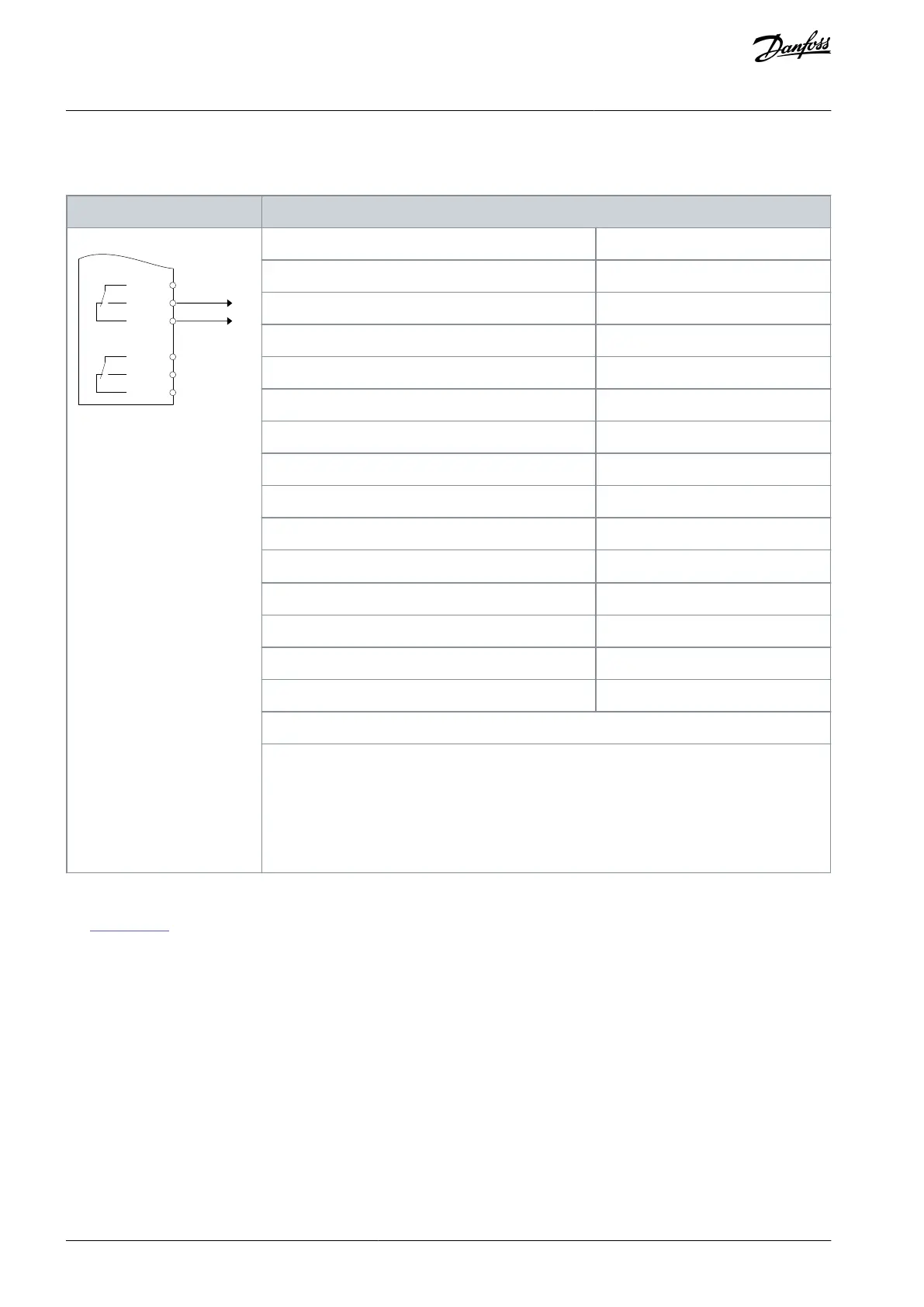
Table 91: Wiring Configuration for a Relay with Smart Logic Control
XD2.21
XD2.22
XD2.23
XD2.24
XD2.25
XD2.26
Parameter 4-30 Motor Feedback Loss Function
Parameter 4-31 Motor Feedback Speed Error
Parameter 4-32 Motor Feedback Loss Timeout
Parameter 7-00 Speed PID Feedback Source
Parameter 17-11 Resolution (PPR)
Parameter 13-00 SL Controller Mode
Parameter 13-01 Start Event
Parameter 13-02 Stop Event
Parameter 13-10 Comparator Operand
Parameter 13-11 Comparator Operator
Parameter 13-12 Comparator Value
Parameter 13-51 SL Controller Event
Parameter 13-52 SL Controller Action
[32] Set digital out A low
Parameter 5-40 Function Relay
Notes/comments:
If the limit in the feedback monitor is exceeded, warning 90, Feedback Mon. is issued. The SLC
monitors warning 90, Feedback Mon. and if the warning becomes true, relay 1 is triggered. Ex-
ternal equipment may require service.
However, if the feedback error goes below the limit again within 5 s and the warning disap-
pears, press [Reset] on the LCP.
8.1.12 Wiring Configuration for a Cascade Controller
See Illustration 69 for an example of a built-in basic cascade controller with 1 variable-speed pump (lead) and 2 fixed-speed pumps,
a 4–20 mA transmitter, and system safety interlock.
AQ262141314214en-000301 / 130R0880128 | Danfoss A/S © 2021.11
Wiring Configuration Examples
VLT® HVAC Drive FC 102
Operating Guide
 Loading...


