EasyManuals Logo
Home>Danfoss>DC Drives>VLT AHF 005

Danfoss VLT AHF 005 User Manual

Danfoss VLT AHF 005
196 pages
To Next Page IconTo Next Page
To Previous Page IconTo Previous Page
Page #129 background imageLoading...
Page #129 background image
Power card
Motor Mains
Relay 1
(cascade
pump 1)
Relay 2
(cascade
pump 2)
+24 V OUT
+ 24 V OUT
(Start)
(Safety interlock)
(Feedback 1 res.)
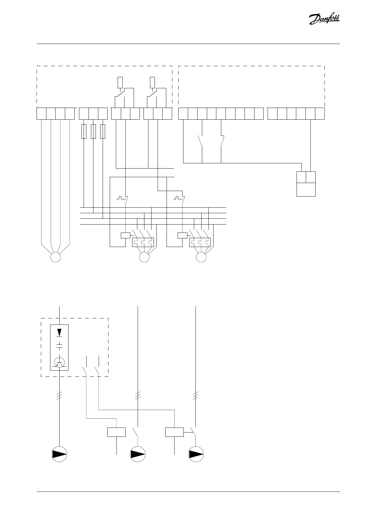
Control compartment/control card
System
start/
stop
From motor control circuitry
System
safety
interlock
Pressure
transmitter
4-20 mA,
L1
L2
L3
Ground
N
e30bu098.10
P
24 V DC
COM D IN
D IN 1
D IN1
D IN1/D OUT
D IN1/D OUT
D IN 1
D IN 1
A IN2
A OUT1
COM A OUT
+ 10 V OUT
A IN1
COM A IN
96
U
97
V
98
W
PE
91
L1
92
L2
93
L3
XD2.
21
XD2.
22
XD2.
23
XD2.
24
XD2.
25
XD2.
26
XD2.
10
XD2.
11
XD2.
12
XD2.
13
XD2.
14
XD2.
15
XD2.
16
XD2.
17
XD2.
18
XD2.
4
XD2.
5
XD2.
6
XD2.
7
XD2.
8
XD2.
9
MMM
Illustration 69: Cascade Controller Wiring Diagram
8.1.13 Wiring Configuration for a Fixed Variable Speed Pump
L1/L2/L3
L1/L2/L3 L1/L2/L3
Relay 1
Relay 2
e30ba376.10
Drive
Illustration 70: Fixed Variable Speed Pump Wiring Diagram
AQ262141314214en-000301 / 130R0880 | 129Danfoss A/S © 2021.11
Wiring Configuration Examples
VLT® HVAC Drive FC 102
Operating Guide

Table of Contents

Other manuals for Danfoss VLT AHF 005

Questions and Answers:

Question and Answer IconNeed help?

Do you have a question about the Danfoss VLT AHF 005 and is the answer not in the manual?

Danfoss VLT AHF 005 Specifications

General IconGeneral
BrandDanfoss
ModelVLT AHF 005
CategoryDC Drives
LanguageEnglish

Related product manuals