This parameter is active only when
parameter 1-10 Motor Construction is set to [3] PM,
salient IPM.
Enter the quadrature axis inductance of the PM
motor. If only phase-to-phase data is available,
divide the phase-to-phase value by 2 to achieve
the phase value.
It is also possible to measure the value with an
inductance meter, which also takes the
inductance of the cable into account. Make 1
rotation of the motor’s rotor and nd the
maximum phase-to-phase inductance value.
Divide the value by 2 and enter the result.
4. Parameter 1-44 d-axis Inductance Sat. (LdSat).
This parameter is active only when
parameter 1-10 Motor Construction is set to [3] PM,
salient IPM.
This parameter corresponds to the saturation
inductance of d-axis. The default value is the
value set in parameter 1-37 d-axis Inductance (Ld).
Do not change the default value in most cases. If
the motor supplier provides the saturation curve,
enter the d-axis inductance value, which is 100%
of the nominal current.
5. Parameter 1-45 q-axis Inductance Sat. (LqSat).
This parameter is active only when
parameter 1-10 Motor Construction is set to [3] PM,
salient IPM.
This parameter corresponds to the saturation
inductance of q-axis. The default value is the
value set in parameter 1-38 q-axis Inductance (Lq).
In most cases, do not change the default. If the
motor supplier provides the saturation curve,
enter the q-axis inductance value, which is 100%
of the nominal current.
Test motor operation
1. Start the motor at low speed (100–200 RPM). If
the motor does not run, check installation,
general programming, and motor data.
2. Check if the start function in parameter 1-70 Start
Mode ts the application requirements.
Rotor detection
This function is the recommended selection for
applications where the motor starts from standstill, for
example pumps or conveyors. For some motors, a sound is
heard when the frequency converter performs the rotor
detection. This sound does not harm the motor. Adjust the
value in parameter 1-46 Position Detection Gain for dierent
motors. If the frequency converter fails to start, or an
overcurrent alarm occurs when the frequency converter
starts, check if the rotor is blocked or not. If the rotor is
not blocked, set parameter 1-70 Start Mode to [1] Parking
and try again.
Parking
This function is the recommended option for applications
where the motor is rotating at low speed, for example
windmilling in fan applications. Parameter 2-06 Parking
Current and parameter 2-07 Parking Time are adjustable.
Increase the factory setting of these parameters for
applications with high inertia.
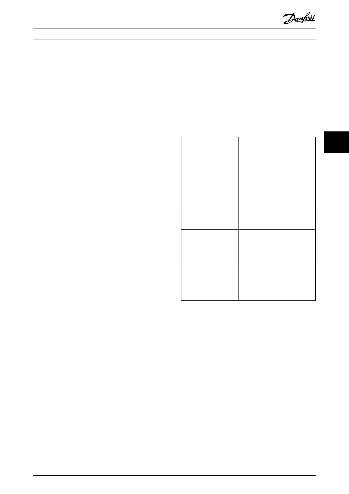
Start the motor at nominal speed. If the application does
not run well, check the VVC
+
PM settings. Table 5.13 shows
recommendations in dierent applications.
Application Settings
Low inertia applications
I
Load
1)
/I
Motor
2)
<5
•
Increase the value for
parameter 1-17 Voltage lter time
const. by factor 5 to 10.
•
Reduce the value for
parameter 1-14 Damping Gain.
•
Reduce the value (<100%) for
parameter 1-66 Min. Current at
Low Speed.
Medium inertia
applications
50>I
Load
/I
Motor
>5
Keep calculated values.
High inertia applications
I
Load
/I
Motor
> 50
Increase the values for
parameter 1-14 Damping Gain,
parameter 1-15 Low Speed Filter Time
Const., and parameter 1-16 High
Speed Filter Time Const.
High load at low speed
<30% (rated speed)
Decrease parameter 1-17 Voltage
lter time const.
Decrease parameter 1-66 Min. Current
at Low Speed (>100% for longer time
can overheat the motor).
Table 5.13 Recommendations in Dierent Applications
1) I
Load
=The inertia of load.
2) I
Motor
=The inertia of motor.
If the motor starts oscillating at a certain speed, increase
parameter 1-14 Damping Gain. Increase the value in small
steps.
Adjust the starting torque in parameter 1-66 Min. Current at
Low Speed. 100% provides nominal torque as starting
torque.
5.5.3 Automatic Motor Adaptation (AMA)
Automatic motor adaptation (AMA)
It is highly recommended to run AMA because it measures
the electrical characteristics of the motor to optimize
compatibility between the frequency converter and the
motor under VVC
+
mode.
Commissioning Quick Guide
MG06A702 Danfoss A/S © 03/2017 All rights reserved. 31
5 5
 Loading...


