7.3 Connections
7.3.1 Power Connections
NOTICE
All cabling must comply with national and local
regulations on cable cross-sections and ambient
temperature. Non-UL applications can use 75 °C (167 °F)
and 90 °C (194 °F) copper conductors.
The power cable connections are located as shown in
Illustration 7.2. See chapter 5 Specications for correct
dimensioning of motor cable cross-section and length.
For protection of the drive, use the recommended fuses
unless the unit has built-in fuses. Recommended fuses are
listed in chapter 7.5 Fuses and Circuit Breakers. Ensure that
proper fusing complies with local regulations.
The connection of mains is
tted to the mains switch if
included.
3 Phase
power
input
130BA026.10
91 (L1)
92 (L2)
93 (L3)
95 PE
Illustration 7.2 Power Cable Connections
NOTICE
The motor cable must be shielded/armored. If an
unshielded/unarmored cable is used, some EMC
requirements are not complied with. Use a shielded/
armored motor cable to comply with EMC emission
specications. For more information, see
chapter 7.14 EMC-compliant Installation.
Shielding of cables
Avoid installation with twisted shield ends (pigtails). They
spoil the shielding eect at higher frequencies. If it is
necessary to break the shield to install a motor isolator or
contactor, continue the shield at the lowest possible HF
impedance.
Connect the motor cable shield to both the decoupling
plate of the drive and the metal housing of the motor.
Make the shield connections with the largest possible
surface area (cable clamp) by using the installation devices
within the drive.
Cable length and cross-section
The drive has been EMC-tested with a given length of
cable. Keep the motor cable as short as possible to reduce
the noise level and leakage currents.
Switching frequency
When drives are used together with sine-wave lters to
reduce the acoustic noise from a motor, the switching
frequency must be set according to the instructions in
parameter 14-01 Switching Frequency.
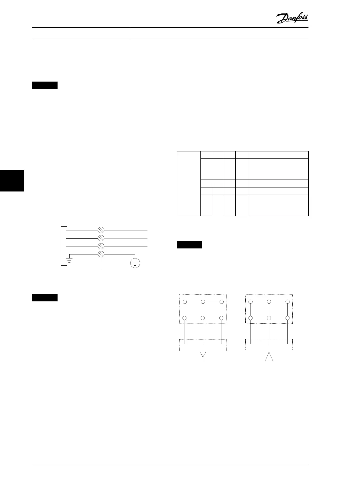
Terminal 96 97 98 99 Description
U V W
PE
1)
Motor voltage 0–100% of
mains voltage. 3 wires out
of motor.
U1 V1 W1
PE
1)
Delta-connected.
W2 U2 V2
PE
1)
6 wires out of motor.
U1 V1 W1
PE
1)
Star-connected U2, V2, W2
U2, V2, and W2 to be
interconnected separately.
Table 7.1 Motor Cable Connection
1) Protected ground connection.
NOTICE
In motors without phase insulation, paper, or other
insulation reinforcement suitable for operation with
voltage supply, use a sine-wave lter on the output of
the drive.
U
1
V
1
W
1
175ZA114.11
96 97 98
96 97 98
FC
FC
Motor
Motor
U
2
V
2
W
2
U
1
V
1
W
1
U
2
V
2
W
2
Illustration 7.3 Motor Cable Connection
Electrical Installation Con... VLT® AutomationDrive FC 361
40 Danfoss A/S © 03/2019 All rights reserved. MG06K102
77
 Loading...


