7.9 IT Mains
Mains supply isolated from ground
If the drive is supplied from an isolated mains source (IT
mains, oating delta, or grounded delta) or TT/TN-S mains
with grounded leg, the RFI switch is recommended to be
turned o via parameter 14-50 RFI Filter on the drive and
parameter 14-50 RFI Filter on the lter. For more detail, see
IEC 364-3. In the o position, the lter capacitors between
the chassis and the DC link are cut o to avoid damage to
the DC link and to reduce the ground capacity currents,
according to IEC 61800-3.
If optimum EMC performance is needed, or parallel motors
are connected, or the motor cable length is above 25 m
(82 ft), Danfoss recommends setting parameter 14-50 RFI
Filter to [ON]. Refer also to the Application Note, VLT on IT
Mains. It is important to use isolation monitors that are
rated for use together with power electronics (IEC
61557-8).
7.10 Eciency
Eciency of the drive (η
VLT
)
The load on the drive has little eect on its eciency. In
general, the eciency is the same at the rated motor
frequency f
M,N
, whether the motor supplies 100% of the
rated shaft torque or only 75%, in case of part loads.
The eciency of the drive does not change even if other
U/f characteristics are selected. However, the U/f character-
istics inuence the eciency of the motor.
The eciency declines slightly when the switching
frequency is set to a value of above 5 kHz. The eciency is
slightly reduced when the mains voltage is 480 V, or if the
motor cable is longer than 30 m (98 ft).
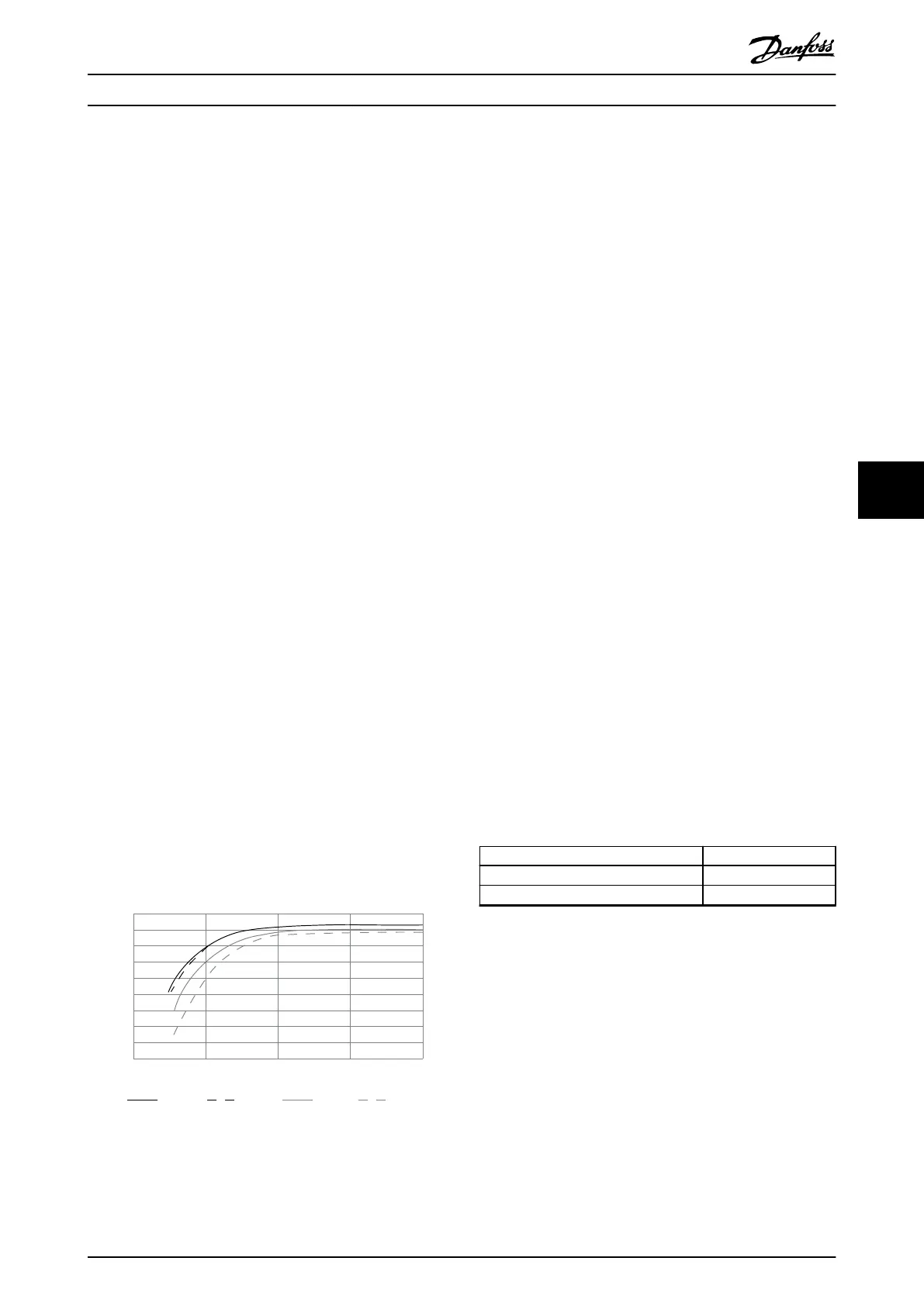
Drive eciency calculation
Calculate the eciency of the drive at dierent speeds and
loads based on Illustration 7.15. The factor in this graph
must be multiplied by the specic eciency factor listed in
the specication tables in chapter 5.1 Electrical Data,
380-480 V.
1.0
0.99
0.98
0.97
0.96
0.95
0.93
0.92
0% 50% 100% 200%
0.94
Relative Eciency
130BB252.11
1.01
150%
% Speed
100% load 75% load 50% load 25% load
Illustration 7.15 Typical
Eciency Curves
Example: Assume a 160 kW, 380–480/500 V AC drive at
25% load at 50% speed. Illustration 7.15 shows 0.97 - rated
eciency for a 160 kW drive is 0.98. The actual eciency is
then: 0.97x 0.98=0.95.
Eciency of the motor (η
MOTOR
)
The eciency of a motor connected to the drive depends
on magnetizing level. In general, the eciency is as good
as with mains operation. The eciency of the motor
depends on the type of motor.
In the range of 75–100% of the rated torque, the eciency
of the motor is practically constant, both when the drive
controls it and when it runs directly on the mains.
In small motors, the inuence from the U/f characteristic
on eciency is marginal. However, in motors from 11 kW
(15 hp) and up, the advantages are signicant.
Typically the switching frequency does not aect the
eciency of small motors. Motors from 11 kW (15 hp) and
up have their eciency improved (1–2%) because the
shape of the motor current sine-wave is almost perfect at
high switching frequency.
Eciency of the system (η
SYSTEM
)
To calculate system eciency, the eciency of the drive
(η
VLT
) is multiplied by the eciency of the motor (η
MOTOR
):
η
SYSTEM
=η
VLT
x η
MOTOR
7.11
Acoustic Noise
The acoustic noise from the drive comes from 3 sources:
•
DC intermediate circuit coils.
•
Internal fans.
•
RFI
lter choke.
Table 7.11 lists the typical acoustic noise values measured
at a distance of 1 m (9 ft) from the unit.
Enclosure size dBA at full fan speed
J8 73
J9 75
Table 7.11 Acoustic Noise
Test results performed according to ISO 3744 for audible
noise magnitude in a controlled environment. Noise tone
has been quantied for engineering data record of
hardware performance per ISO 1996-2 Annex D.
Electrical Installation Con... Design Guide
MG06K102 Danfoss A/S © 03/2019 All rights reserved. 49
7 7
 Loading...


