7.12 dU/dt Conditions
NOTICE
To avoid the premature aging of motors that are not
designed to be used with drives, such as those motors
without phase insulation paper or other insulation
reinforcement, Danfoss strongly recommends a dU/dt
lter or a sine-wave lter tted on the output of the
drive. For further information about dU/dt and sine-wave
lters, see the Output Filters Design Guide.
When a transistor in the inverter bridge switches, the
voltage across the motor increases by a dU/dt ratio
depending on the motor cable (type, cross-section, length
shielded or unshielded) and the inductance.
The natural induction causes an overshoot U
PEAK
in the
motor voltage before it stabilizes itself at a level
depending on the voltage in the intermediate circuit. The
rise time and the peak voltage U
PEAK
aect the service life
of the motor. In particular, motors without phase coil
insulation are aected if the peak voltage is too high.
Motor cable length aects the rise time and peak voltage.
If the motor cable is short (a few meters), the rise time and
peak voltage are lower. If the motor cable is long (100 m
(328 ft)), the rise time and peak voltage are higher.
Peak voltage on the motor terminals is caused by the
switching of the IGBTs. The drive complies with the
demands of IEC 60034-25:2007 edition 2.0 regarding
motors designed to be controlled by drives. The drive also
complies with IEC 60034-17:2006 edition 4 regarding Norm
motors controlled by drives.
High-power range
The power sizes in Table 7.12 to Table 7.13 at the
appropriate mains voltages comply with the requirements
of IEC 60034-17:2006 edition 4 regarding normal motors
controlled by drives, IEC 60034-25:2007 edition 2.0
regarding motors designed to be controlled by drives, and
NEMA MG 1-1998 Part 31.4.4.2 for inverter-fed motors. The
power sizes in Table 7.12 to Table 7.13 do not comply with
NEMA MG 1-1998 Part 30.2.2.8 for general purpose motors.
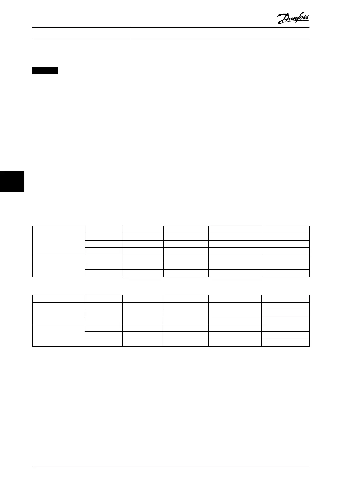
7.12.1 dU/dt Test Results for Enclosures J8–J9
Power size [kW (hp)] Cable [m (ft)] Mains voltage [V]
Rise time [µs]
Peak voltage [V]
dU/dt [V/µs]
90–160 (125–250) 30 (98) 500 0.71 1180 1339
150 (492) 500 0.76 1423 1497
300 (984) 500 0.91 1557 1370
200–315 (300–450) 30 (98) 500 1.10 1116 815
150 (492) 500 2.53 1028 321
300 (984) 500 1.29 835 517
Table 7.12 IEC dU/dt Test Results for J8–J9 with Unshielded Cables and No Output Filter, 380–480 V
Power size [kW (hp)] Cable [m (ft)] Mains voltage [V]
Rise time [µs]
Peak voltage [V]
dU/dt [V/µs]
90–160 (125–250) 30 (98) 500 – – –
150 (492) 500 0.66 1418 1725
300 (984) 500 0.96 1530 1277
200–315 (300–450) 30 (98) 500 – – –
150 (492) 500 0.56 1261 1820
300 (984) 500 0.78 1278 1295
Table 7.13 IEC dU/dt Test Results for J8–J9 with Shielded Cables and No Output Filter, 380–480 V
Electrical Installation Con... VLT® AutomationDrive FC 361
50 Danfoss A/S © 03/2019 All rights reserved. MG06K102
77
 Loading...


