11.3 RS485 Installation and Set-up
RS485 is a 2-wire bus interface compatible with multi-drop
network topology. Nodes can be connected as a bus, or via
drop cables from a common trunk line. A total of 32 nodes
can be connected to 1 network segment.
Repeaters divide network segments. Note each repeater
function as a node within the segment in which it is
installed. Each node connected within a given network
must have a unique node address, across all segments.
Terminate each segment at both ends, using either the
termination switch (S801) of the drives or a biased
termination resistor network. Always use shielded twisted
pair (STP) cable for bus cabling, and always follow good
common installation practice.
Low-impedance ground connection of the shield at every
node is important, including at high frequencies. Thus,
connect a large surface of the shield to ground, for
example, with a cable clamp or a conductive cable gland.
If necessary, apply potential-equalizing cables to maintain
the same ground potential throughout the network, partic-
ularly in installations with long cables.
To prevent impedance mismatch, always use the same
type of cable throughout the entire network. When
connecting a motor to the drive, always use shielded
motor cable.
Cable Shielded twisted pair (STP)
Impedance
120 Ω
Cable length Maximum 1200 m (3937 ft), including drop
lines.
Maximum 500 m (1640.5 ft) station-to-
station
Table 11.2 Motor Cable
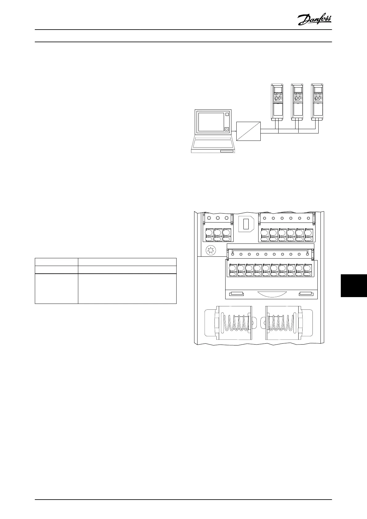
One or more drives can be connected to a control (or
master) using the RS485 standardized interface. Terminal
68 is connected to the P signal (TX+, RX+), while terminal
69 is connected to the N signal (TX-, RX-). See illustrations
in chapter 7.14 EMC-compliant Installation.
If more than 1 drive is connected to a master, use parallel
connections.
130BA060.11
68 69 68 69 68 69
RS 485
RS 232
USB
+
-
Illustration 11.2 Parallel Connections
To avoid potential equalizing currents in the shield, ground
the cable shield via terminal 61, which is connected to the
frame via an RC-link.
e30bh258.10
12 13 18 19 27 29 32
33
20
61
68
69 39 42 50 53 54 55
Illustration 11.3 Control Card Terminals
The RS485 bus must be terminated by using a resistor
network at both ends. For this purpose, set switch S801 on
the control card to "ON".
For more information, see chapter 7.2 Wiring Schematic.
Communication protocol must be set to
parameter 8-30 Protocol.
Appendix Design Guide
MG06K102 Danfoss A/S © 03/2019 All rights reserved. 77
11 11
 Loading...


