3.2.4 Cooling and Airflow
Cooling
Cooling can be obtained in different ways, by using the
cooling ducts in the bottom and the top of the unit, by
taking air in and out the back of the unit or by combining
the cooling possibilities.
Duct cooling
A dedicated option has been developed to optimize instal-
lation of frequency converters in Rittal TS8 enclosures
utilizing the fan of the frequency converter for forced air
cooling of the backchannel. The air out the top of the
enclosure could but ducted outside a facility so the heat
loses from the backchannel are not dissipated within the
control room reducing air-conditioning requirements of the
facility.
Back cooling
The backchannel air can also be ventilated in and out the
back of a Rittal TS8 enclosure. This offers a solution where
the backchannel could take air from outside the facility
and return the heat loses outside the facility thus reducing
air-conditioning requirements.
Airflow
The necessary airflow over the heat sink must be secured.
The flow rate is shown below.
Enclosure
protection
Door fan(s) / Top fan
airflow
Heatsink fan(s)
IP21/NEMA 1
700 m
3
/h (412 cfm)* 985 m
3
/h (580 cfm)*
IP54/NEMA 12
525 m
3
/h (309 cfm)* 985 m
3
/h (580 cfm)*
Table 3.1 Heatsink Air Flow
* Airflow per fan. Frame size F contain multiple fans.
NOTE
The fan runs for the following reasons:
1. AMA
2. DC Hold
3. Pre-Mag
4. DC Brake
5. 60% of nominal current is exceeded
6. Specific heatsink temperature exceeded (power
size dependent).
Once the fan is started it will run for minimum 10 minutes.
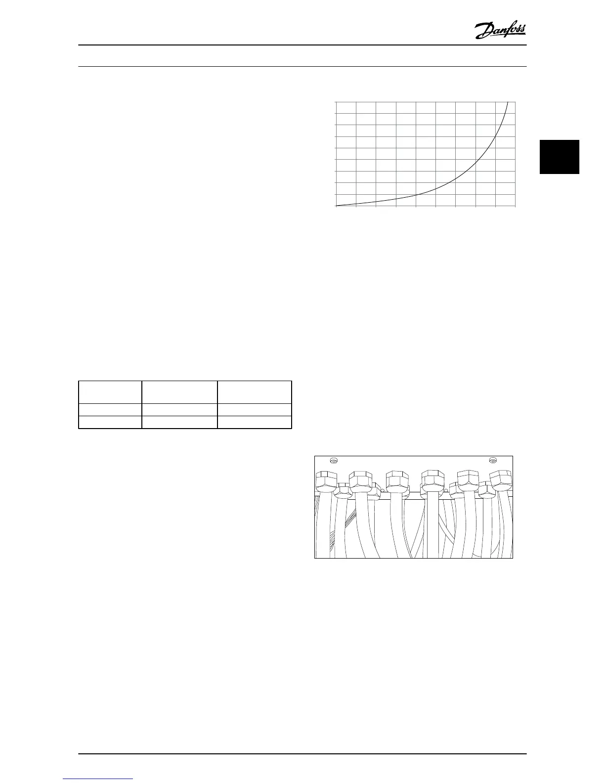
External ducts
If additional duct work is added externally to the Rittal
cabinet the pressure drop in the ducting must be
calculated. Use the charts below to derate the frequency
converter according to the pressure drop.
Illustration 3.19 F frame Derating vs. Pressure Change (Pa)
Drive air flow: 985 m
3
/h (580 cfm)
3.2.5
Gland/Conduit Entry - IP21 (NEMA 1)
and IP54 (NEMA12)
Cables are connected through the gland plate from the
bottom. Remove the plate and plan where to place the
entry for the glands or conduits. Prepare holes in the
marked area on the drawing.
NOTE
The gland plate must be fitted to the frequency converter
to ensure the specified protection degree, as well as
ensuring proper cooling of the unit. If the gland plate is
not mounted, the frequency converter may trip on Alarm
69, Pwr. Card Temp
 Loading...


