3.2 Mechanical Installation
Preparation of the mechanical installation of the frequency
converter must be done carefully to ensure a proper result
and to avoid additional work during installation. Start
taking a close look at the mechanical drawings at the end
of this instruction to become familiar with the space
demands.
3.2.1 Tools Needed
To perform the mechanical installation the following tools
are needed:
•
Drill with 10 or 12 mm drill
•
Tape measure
•
Wrench with relevant metric sockets (7-17 mm)
•
Extensions to wrench
•
Sheet metal punch for conduits or cable glands
in IP21/Nema 1 and IP54 units
•
Lifting bar to lift the unit (rod or tube max. Ø 25
mm (1 inch), able to lift minimum 400 kg (880
lbs)).
•
Crane or other lifting aid to place the frequency
converter in position
3.2.2
General Considerations
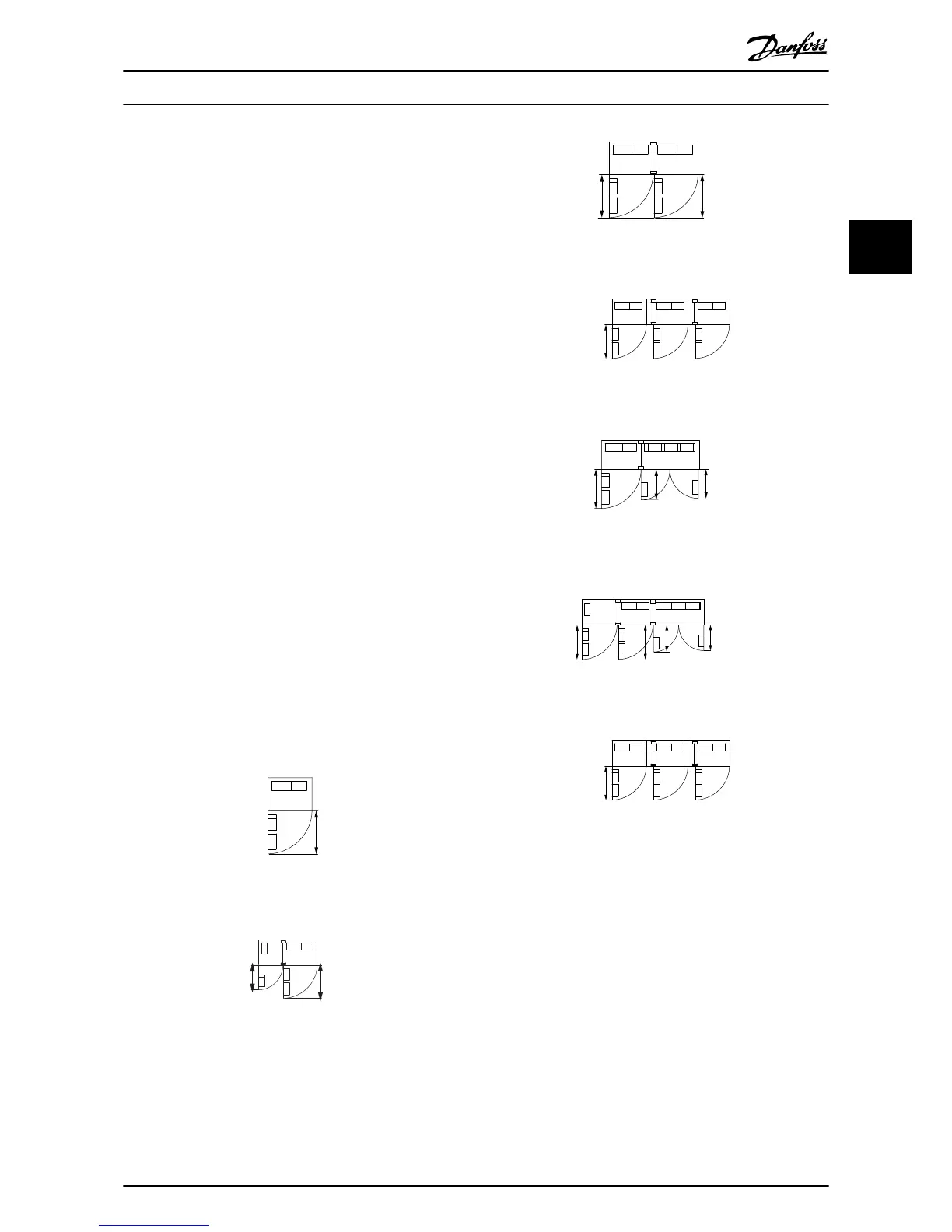
Space
Ensure proper space above and below the frequency
converter to allow airflow and cable access. In addition
space in front of the unit must be considered to enable
opening of the door of the panel.
Illustration 3.10 Space in front of IP21/IP54 enclosure type, frame
size F14
Wire access
Ensure that proper cable access is present including
necessary bending allowance.
NOTE
All cable lugs/shoes must mount within the width of the
terminal bus bar.
How to Install
VLT
®
Automation Drive FC 300 12-Pulse
Operating Instructions High Power
MG34Q202 - VLT
®
is a registered Danfoss trademark 15
3
3
 Loading...


