4.
Modify the inverter waveform, 60° AVM vs.
SFAVM
5. Install a shaft grounding system or use an
isolating coupling
6. Apply conductive lubrication
7. Use minimum speed settings if possible
8. Try to ensure the line voltage is balanced to
ground. This can be difficult for IT, TT, TN-CS or
Grounded leg systems
9. Use a dU/dt or sinus filter
3.3.17
Brake Resistor Temperature Switch
Torque: 0.5-0.6 Nm (5 in-lbs)
Screw size: M3
This input can be used to monitor the temperature of an
externally connected brake resistor. If the input between
104 and 106 is established, the frequency converter will
trip on warning/alarm 27, “Brake IGBT”. If the connection is
closed between 104 and 105, the frequency converter will
trip on warning/alarm 27, “Brake IGBT”.
A KLIXON switch must be installed that is `normally
closed'. If this function is not used, 106 and 104 must be
short-circuited together.
Normally closed: 104-106 (factory installed jumper)
Normally open: 104-105
Terminal No.
Function
106, 104, 105 Brake resistor temperature switch.
If the temperature of the brake resistor gets too high and
the thermal switch drops out, the frequency converter will
stop braking. The motor will start coasting.
175ZA877.10
106
NC
104
C
105
NO
3.3.18 Control Cable Routing
Tie down all control wires to the designated control cable
routing as shown in the picture. Remember to connect the
shields in a proper way to ensure optimum electrical
immunity.
Fieldbus connection
Connections are made to the relevant options on the
control card. For details, see the relevant fieldbus
instruction. The cable must be placed in the provided path
inside the frequency converter and tied down together
with other control wires.
Installation of 24 V external DC Supply
Torque: 0.5 - 0.6 Nm (5 in-lbs)
Screw size: M3
No. Function
35 (-), 36 (+) 24 V external DC supply
24 V DC external supply can be used as low-voltage supply
to the control card and any option cards installed. This
enables full operation of the LCP (including parameter
setting) without connection to mains. A warning of low
voltage is given when 24 V DC has been connected;
however, there is no tripping.
WARNING
Use 24 V DC supply of type PELV to ensure correct
galvanic isolation (type PELV) on the control terminals of
the frequency converter.
3.3.19 Access to Control Terminals
All terminals to the control cables are located beneath the
LCP. They are accessed by opening the door of the IP21/
54 version or removing the covers of the IP00 version.
3.3.20
Electrical Installation, Control
Terminals
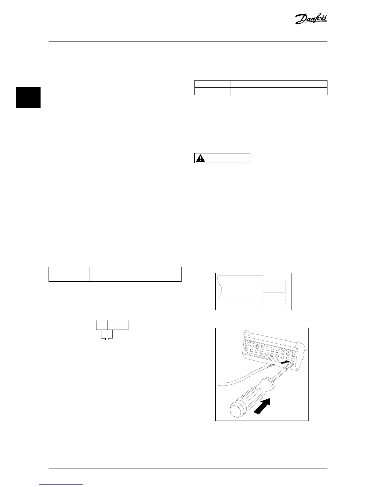
To connect the cable to the terminal:
1. Strip insulation by about 9-10 mm
130BA150.10
9 - 10 mm
(0.37 in)
2.
Insert a screwdriver
1)
in the square hole.
3. Insert the cable in the adjacent circular hole.
4. Remove the screwdriver. The cable is now
mounted in the terminal.
To remove the cable from the terminal:
1.
Insert a screw driver
1)
in the square hole.
How to Install
VLT
®
Automation Drive FC 300 12-Pulse
Operating Instructions High Power
46 MG34Q202 - VLT
®
is a registered Danfoss trademark
3
3
 Loading...


