F14 requirements: Motor phase cable quantities must be
multiples of 4, resulting in 4, 8, 12, or 16 (1, 2, or 3 cables
are not allowed) to obtain an equal amount of wires
attached to each inverter module terminal. The wires are
required to be equal length within 10% between the
inverter module terminals and the first common point of a
phase. The recommended common point is the motor
terminals.
Output junction box requirements: The length, minimum
2.5 m, and quantity of cables must be equal from each
inverter module to the common terminal in the junction
box.
NOTE
If a retrofit applications requires unequal amount of wires
per phase, consult the factory for requirements and
documentation or use the top/bottom entry side cabinet
option.
3.3.9 Brake Cable Drives with Factory
Installed Brake Chopper Option
(Only standard with letter B in position 18 of typecode).
The connection cable to the brake resistor must be
screened and the max. length from frequency converter to
the DC bar is limited to 25 m (82 ft).
Terminal No.
Function
81, 82 Brake resistor terminals
The connection cable to the brake resistor must be
screened. Connect the screen by means of cable clamps to
the conductive back plate at the frequency converter and
to the metal cabinet of the brake resistor.
Size the brake cable cross-section to match the brake
torque. See also Brake Instructions, MI.90.Fx.yy and MI.
50.Sx.yy for further information regarding safe installation.
WARNING
Note that voltages up to 1099 V DC, depending on the
supply voltage, may occur on the terminals.
F Frame Requirements
The brake resistor(s) must be connected to the brake
terminals in each inverter module.
3.3.10
Shielding against Electrical Noise
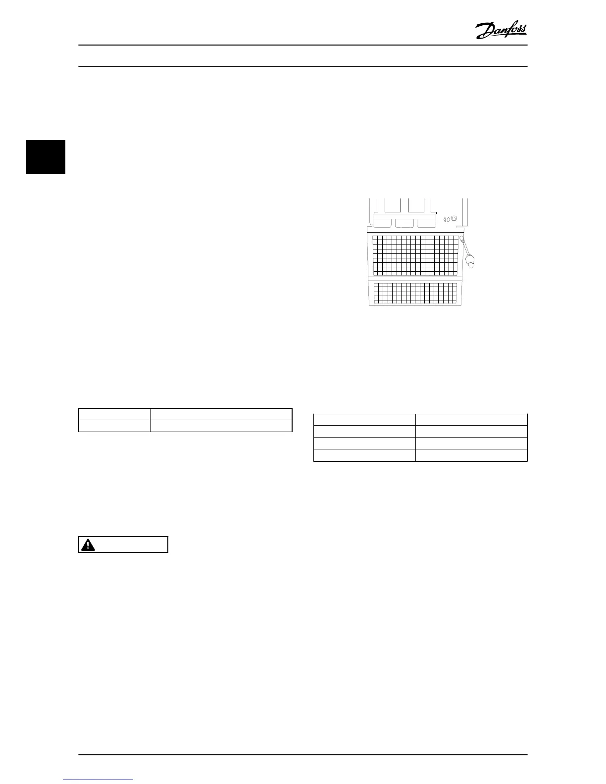
Before mounting the mains power cable, mount the EMC
metal cover to ensure best EMC performance.
NOTE
The EMC metal cover is only included in units with an RFI
filter.
Illustration 3.32 Mounting of EMC shield.
3.3.11 Mains Connection
Mains must be connected to terminals 91-1, 92-1, 93-1,
91-2, 92-2 and 93-2 (see Table 3.3). Earth is connected to
the terminal to the right of terminal 93.
Terminal No.
Function
91-1, 92-1, 93-1 Mains R1/L1-1, S1/L2-1, T1/L3-1
91-2, 92-2, 93-2 Mains R2/L1-2, S2/L2-2, T2/L3-2
94 Earth
NOTE
Check the name plate to ensure that the mains voltage of
the frequency converter matches the power supply of your
plant.
Ensure that the power supply can supply the necessary
current to the frequency converter.
If the unit is without built-in fuses, ensure that the
appropriate fuses have the correct current rating.
How to Install
VLT
®
Automation Drive FC 300 12-Pulse
Operating Instructions High Power
40 MG34Q202 - VLT
®
is a registered Danfoss trademark
3
3
 Loading...


