3.5.2 Switches S201, S202, and S801
Switches S201 (A53) and S202 (A54) are used to select a
current (0-20 mA) or a voltage (-10 to 10 V) configuration
of the analog input terminals 53 and 54 respectively.
Switch S801 (BUS TER.) can be used to enable termination
on the RS-485 port (terminals 68 and 69).
See Illustration 3.33.
Default setting:
S201 (A53) = OFF (voltage input)
S202 (A54) = OFF (voltage input)
S801 (Bus termination) = OFF
NOTE
When changing the function of S201, S202 or S801 be
careful not to use force for the switch over. It is
recommended to remove the LCP fixture (cradle) when
operating the switches. The switches must not be operated
with power on the frequency converter.
130BT310.10
1
2
N O
V LT
BUS TER.
OFF-ON
A53 A54
U- I U- I
3.6 Final Set-Up and Test
To test the set-up and ensure that the frequency converter
is running, follow these steps.
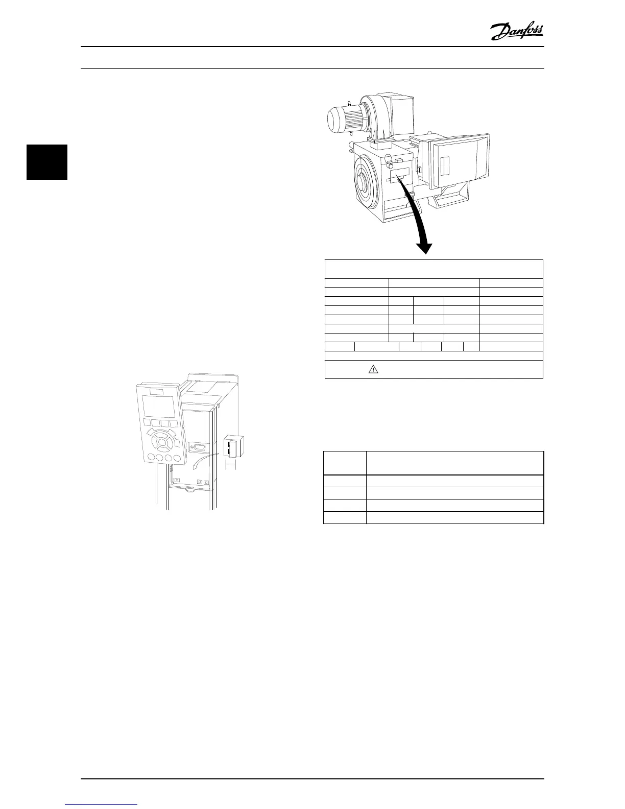
Step 1. Locate the motor name plate
NOTE
The motor is either star- (Y) or delta- connected (Δ). This
information is located on the motor name plate data.
THREE PHASE INDUCTION MOTOR
kW
400
MOD
MCV 315E
Nr.
135189 12 04
PRIMARY
SECONDARY
V
690
A
V A
V A
V A
410.6 CONN Y
CONN
CONN
CONN ENCLOSURE
CAUTION
COS f
ALT
RISE
m
SF
1.15
0.85
AMB
40
1000
80
°C
°C
IP23
40
IL/IN
6.5
HP
536
mm
1481
Hz
DESIGN
50
N
DUTY
INSUL WEIGHT 1.83 ton
EFFICIENCY %
95.8% 95.8% 75%100%
S1
I
130BA767.10
Step 2. Enter the motor name plate data in this parameter
list.
To access this list first press [Quick Menu] then select “Q2
Quick Setup”.
1.
1-20 Motor Power [kW]
1-21 Motor Power [HP]
2.
1-22 Motor Voltage
3.
1-23 Motor Frequency
4.
1-24 Motor Current
5.
1-25 Motor Nominal Speed
Step 3. Activate the Automatic Motor Adaptation (AMA)
Performing an AMA will ensure optimum performance.
The AMA measures the values from the motor model
equivalent diagram.
1. Connect terminal 37 to terminal 12 (if terminal 37
is available).
2. Connect terminal 27 to terminal 12 or set
5-12 Terminal 27 Digital Input to 'No function'
(5-12 Terminal 27 Digital Input [0])
3.
Activate the AMA 1-29 Automatic Motor
Adaptation (AMA).
4. Choose between complete or reduced AMA. If a
Sine-wave filter is mounted, run only the reduced
AMA, or remove the Sine-wave filter during the
AMA procedure.
5. Press [OK]. The display shows “Press [Hand on] to
start”.
How to Install
VLT
®
Automation Drive FC 300 12-Pulse
Operating Instructions High Power
52 MG34Q202 - VLT
®
is a registered Danfoss trademark
3
3
 Loading...


