Very long control cables and analogue signals may in rare
cases and depending on installation result in 50/60 Hz
earth loops due to noise from mains supply cables.
If this occurs, it may be necessary to break the screen or
insert a 100 nF capacitor between screen and chassis.
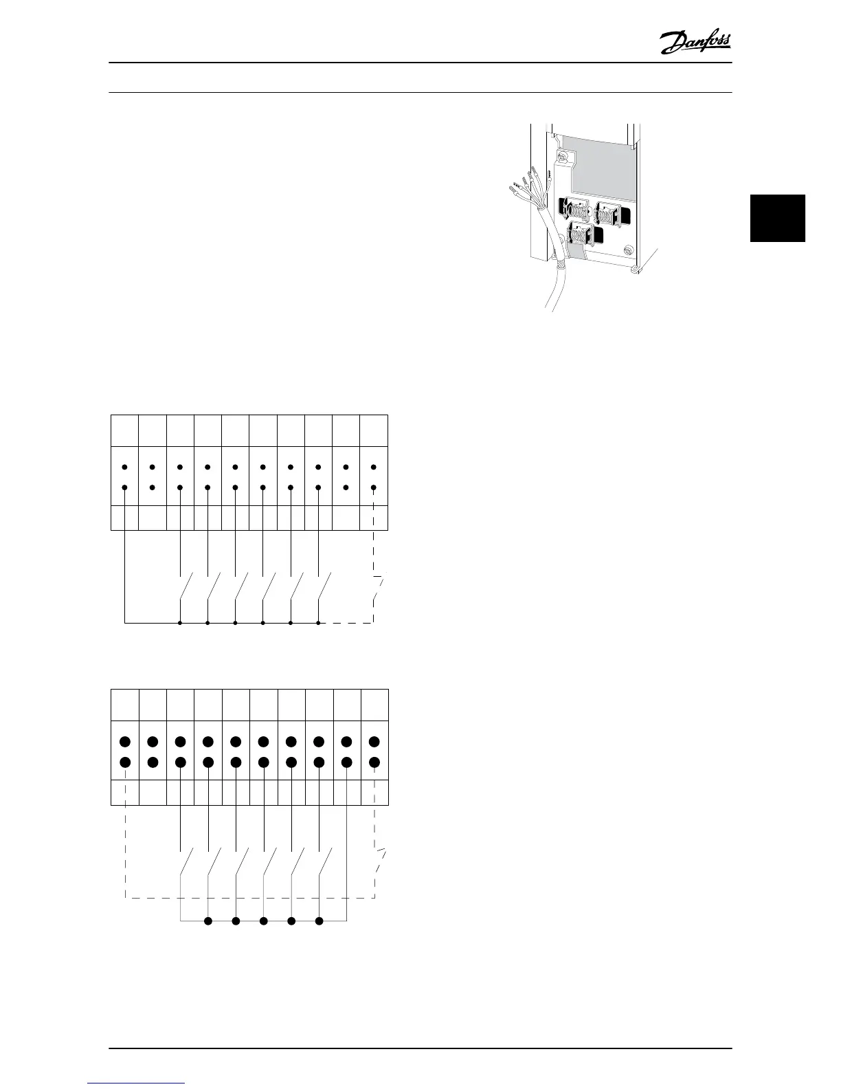
The digital and analog inputs and outputs must be
connected separately to the frequency converter common
inputs (terminal 20, 55, 39) to avoid earth currents from
both groups to affect other groups. For example, switching
on the digital input may disturb the analog input signal.
Input polarity of control terminals
Connect the wires as described in the VLT
®
Automa-
tionDrive FC 300 Operating Instructions, MG33AXYY.
Remember to connect the shields in a proper way to
ensure optimum electrical immunity.
How to Install
VLT
®
Automation Drive FC 300 12-Pulse
Operating Instructions High Power
MG34Q202 - VLT
®
is a registered Danfoss trademark 51
3
3
 Loading...


