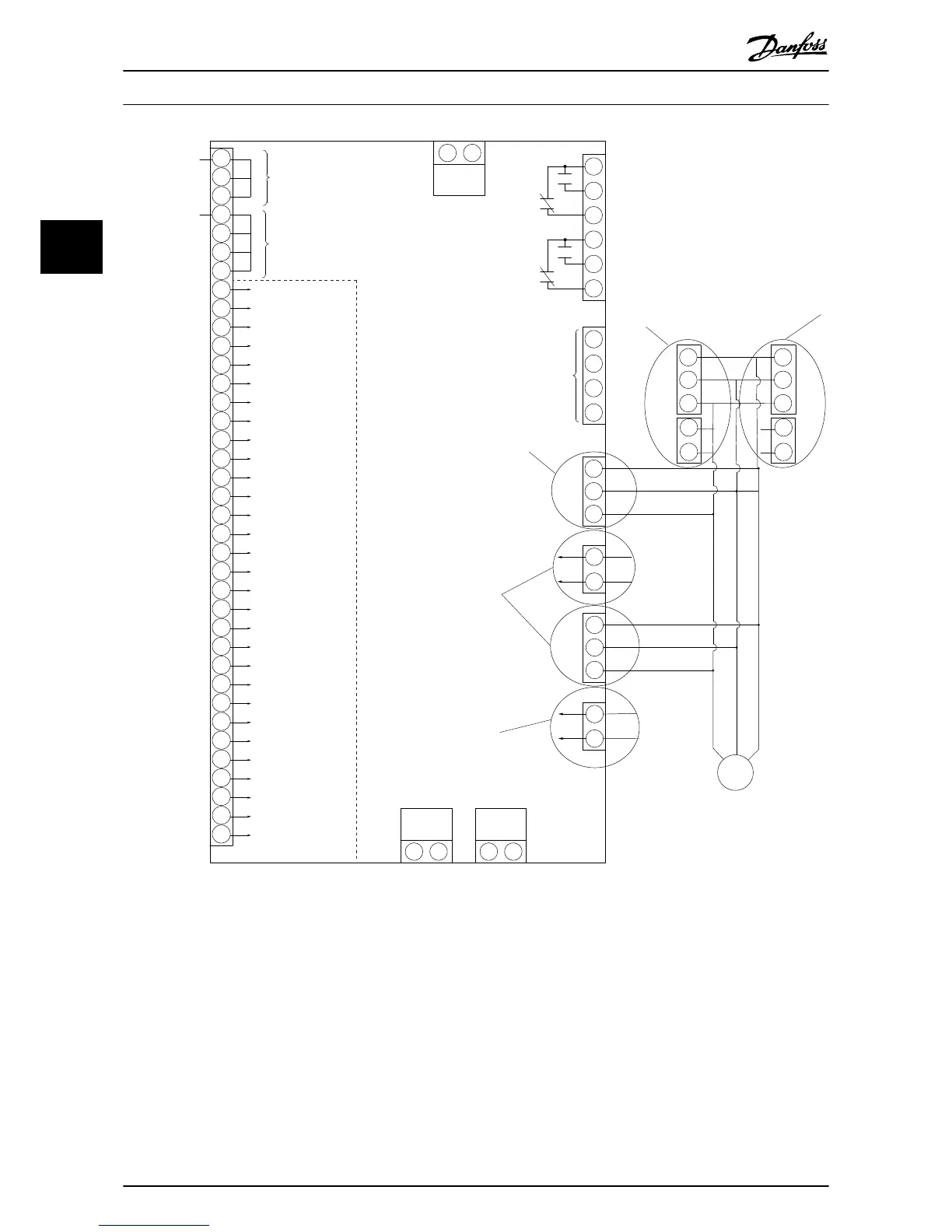
Illustration 3.33 Diagram showing all electrical terminals with NAMUR option shown in dotted line box.
Terminal 37 is the input to be used for Safe Stop. For instructions on Safe Stop installation please refer to the section Safe Stop Instal-
lation in the Design Guide. See also sections Safe Stop and Safe Stop Installation.
1) F8/F9 = (1) set of terminals.
2) F10/F11 = (2) sets of terminals.
3) F12/F13 = (3) sets of terminals.
4) F14 = (4) sets of terminals.
How to Install
VLT
®
Automation Drive FC 300 12-Pulse
Operating Instructions High Power
50 MG34Q202 - VLT
®
is a registered Danfoss trademark
3
3
 Loading...


