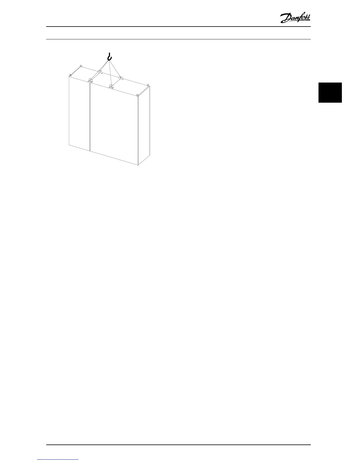
Illustration 3.3 Recommended lifting method, frame size
F11/F12/F13/F14.
NOTE
The plinth is provided in the same packaging as the
frequency converter but is not attached during shipment.
The plinth is required to allow airflow to the frequency
converter to provide proper cooling. The F frames should
be positioned on top of the plinth in the final installation
location. The angle from the top of the frequency
converter to the lifting cable should be 60° or greater.
In addition to the drawings above a spreader bar is an
acceptable way to lift the F Frame.
How to Install
VLT
®
Automation Drive FC 300 12-Pulse
Operating Instructions High Power
MG34Q202 - VLT
®
is a registered Danfoss trademark 9
3
3
 Loading...


