1.1 Purpose of the Manual
This manual is intended to provide detailed information for
the installation and start-up of the adjustable frequency
drive. chapter 2 Installation provides requirements for
mechanical and electrical installation, including input,
motor, control and serial communications wiring and
control terminal functions. chapter 3 Start-up and Functional
Test provides detailed procedures for start-up, basic
operational programming, and functional testing. The
remaining chapters provide supplementary details. These
details include user interface, detailed programming,
application examples, start-up troubleshooting, and specifi-
cations.
1.2 Product Overview
An adjustable frequency drive is an electronic motor
controller that converts AC line power input into a variable
AC waveform output. The frequency and voltage of the
output are regulated to control the motor speed or torque.
The adjustable frequency drive can vary the speed of the
motor in response to system feedback, such as changing
temperature or pressure for controlling fan, compressor, or
pump motors. The adjustable frequency drive can also
regulate the motor by responding to remote commands
from external controllers.
In addition, the adjustable frequency drive monitors the
system and motor status, issues warnings or alarms for
fault conditions, starts and stops the motor, optimizes
energy efficiency, and offers many more control,
monitoring, and efficiency functions. Operation and
monitoring functions are available as status indications to
an outside control system or serial communication
network.
1.3
Internal Adjustable Frequency Drive
Controller Functions
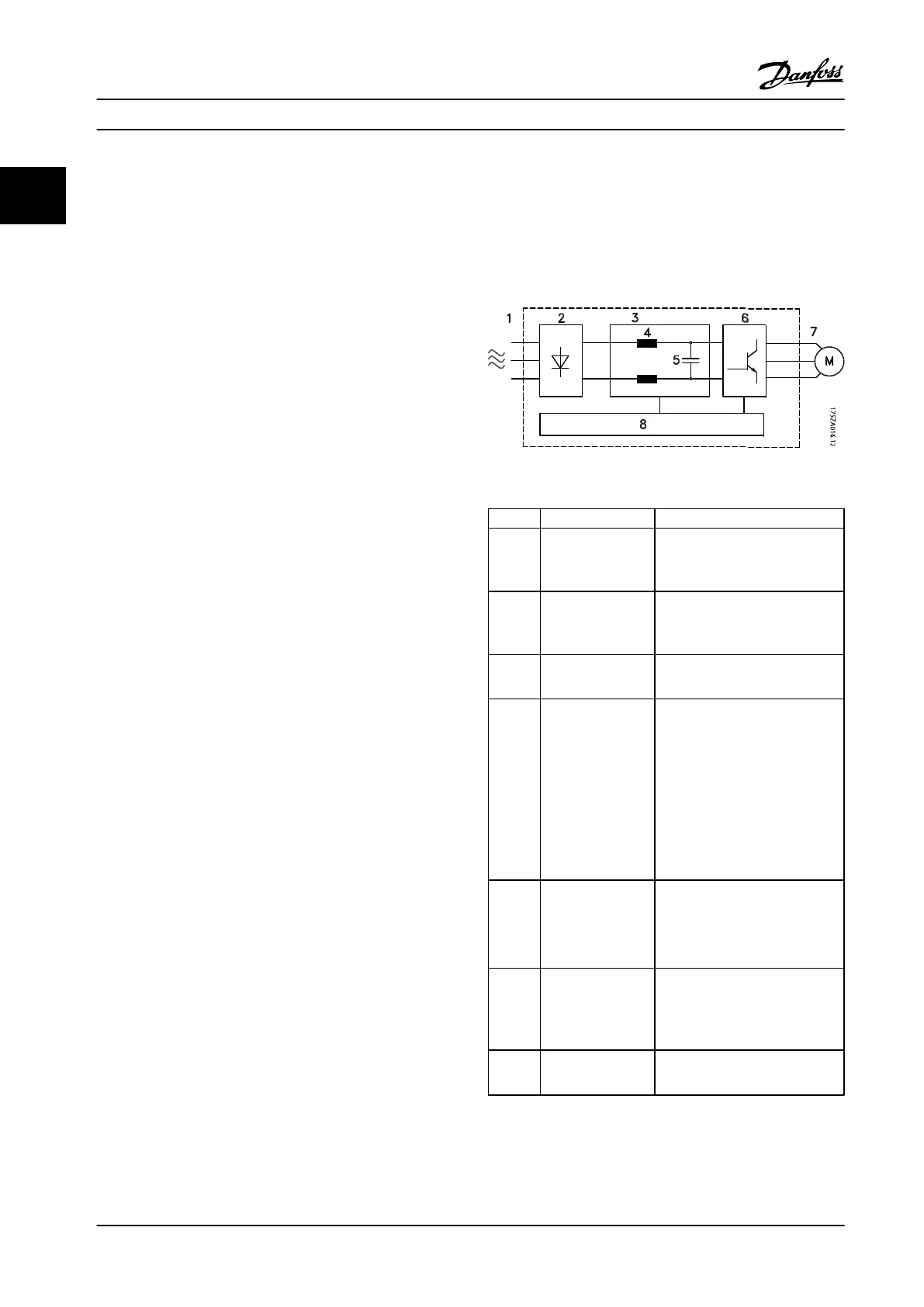
Figure 1.3 is a block diagram of the adjustable frequency
drive's internal components. See Table 1.3 for their
functions.
Figure 1.3 Adjustable Frequency Drive Block Diagram
Area Title Functions
1 Line power input
•
Three-phase AC line power
supply to the adjustable
frequency drive
2 Rectifier
•
The rectifier bridge converts
the AC input to DC current to
supply inverter power
3 DC bus
•
Intermediate DC bus circuit
handles the DC current
4 DC reactors
•
Filter the intermediate DC
circuit voltage
•
Prove line transient protection
•
Reduce RMS current
•
Raise the power factor
reflected back to the line
•
Reduce harmonics on the AC
input
5 Capacitor bank
•
Stores the DC power
•
Provides ride-through
protection for short power
losses
6 Inverter
•
Converts the DC into a
controlled PWM AC waveform
for a controlled variable
output to the motor
7 Output to motor
•
Regulated three-phase output
power to the motor
Introduction Instruction Manual
6 Danfoss A/S © Rev. 2014-02-10 All rights reserved. MG16E222
11
 Loading...


