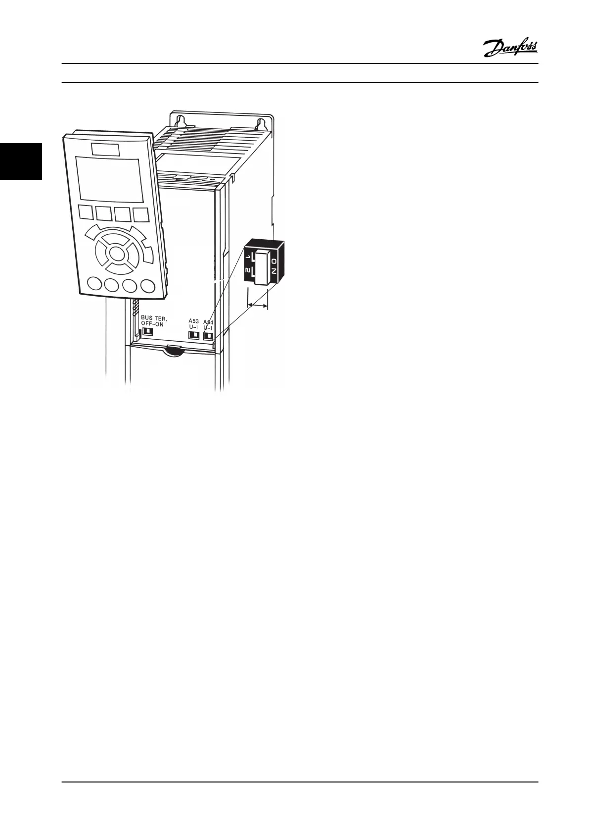
Figure 2.35 Location of Terminals 53 and 54 Switches
2.4.6.6
Terminal 37
Terminal 37 Safe Torque Off (STO) function
The adjustable frequency drive is available with optional
STO functionality via control terminal 37. STO disables the
control voltage of the power semiconductors of the
adjustable frequency drive output stage which in turn
prevents generating the voltage required to rotate the
motor. When the STO (T37) is activated, the adjustable
frequency drive issues an alarm, trips the unit, and coasts
the motor to a stop. Manual restart is required. The STO
function can be used for stopping the adjustable
frequency drive in emergency stop situations. In normal
operating mode when STO is not required, use the
adjustable frequency drive's regular stop function instead.
When automatic restart is used, the requirements
according to ISO 12100-2 paragraph 5.3.2.5 must be
fulfilled.
Liability conditions
Ensure that personnel installing and operating the STO
function:
•
Read and understand the safety regulations
concerning health and safety/accident prevention
•
Understand the generic and safety guidelines
given in this description and the extended
description in the Design Guide
•
Have a good knowledge of the generic and safety
standards applicable to the specific application
Standards
Use of STO on terminal 37 requires that the user satisfies
all provisions for safety including relevant laws, regulations
and guidelines. The optional STO function complies with
the following standards.
EN 954-1: 1996 Category 3
IEC 60204-1: 2005 category 0 – uncontrolled stop
IEC 61508: 1998 SIL2
IEC 61800-5-2: 2007 – safe torque off (STO)
function
IEC 62061: 2005 SIL CL2
ISO 13849-1: 2006 Category 3 PL d
ISO 14118: 2000 (EN 1037) – prevention of
unexpected start-up
The information and instructions in the instruction manual
are not sufficient for a proper and safe use of the STO
functionality. The related information and instructions in
the relevant Design Guide must be followed.
Protective measures
•
Safety engineering systems may only be installed
and commissioned by qualified and skilled
personnel
•
The unit must be installed in an IP54 cabinet or
in an equivalent environment
•
The cable between terminal 37 and the external
safety device must be short-circuit-protected
according to ISO 13849-2 table D.4
•
If any external forces influence the motor axis
(e.g., suspended loads), additional measures (e.g.,
a safety holding brake) are required in order to
eliminate hazards
Installation
Instruction Manual
26 Danfoss A/S © Rev. 2014-02-10 All rights reserved. MG16E222
22
 Loading...


