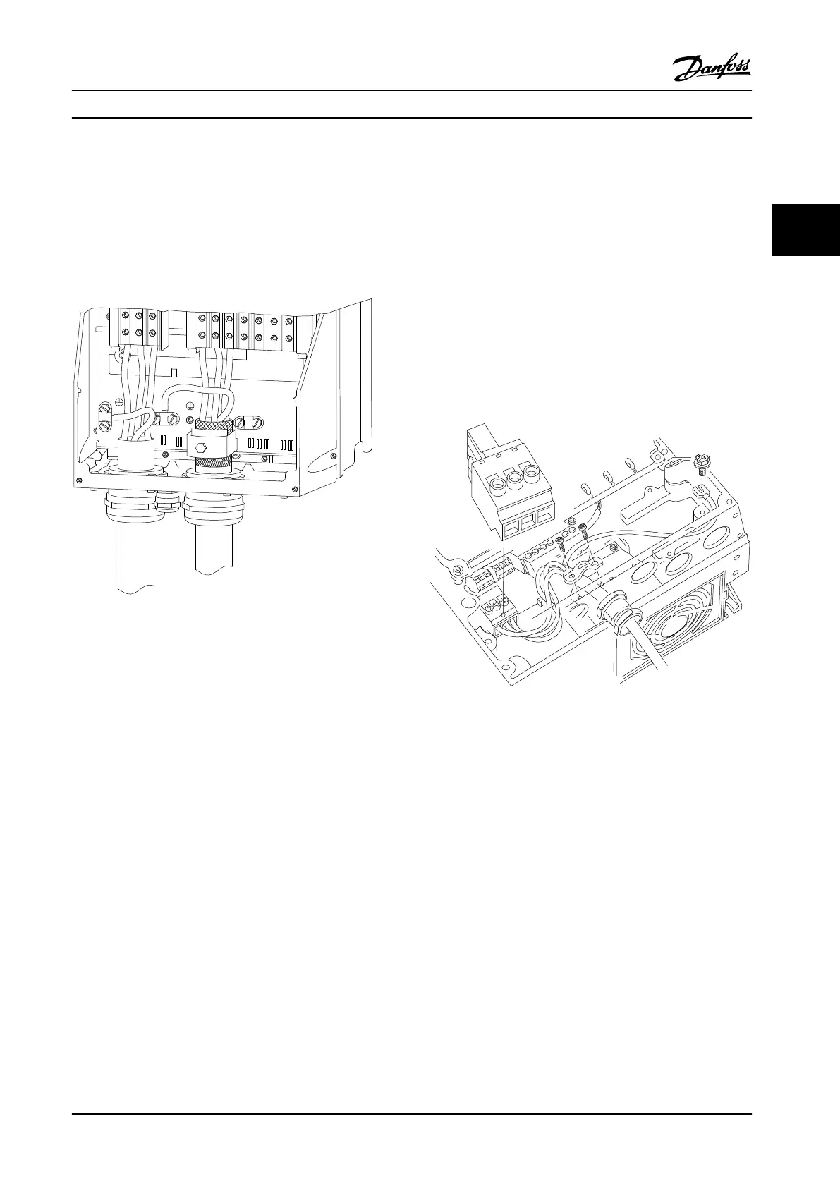
2.4.4.4 Motor Connection for C1 and C2
1. Terminate the motor ground
2. Place motor U, V and W wires in terminal and
tighten
3. Ensure that the outer insulation of the motor
cable is removed under the EMC clamp
91
L1
92
L2
93
L3
96
U
97
V
98
W
88
DC-
89
DC+
81
R-
8
R+
130BA390.11
99
95
Figure 2.18 Motor Connection for C1 and C2
2.4.5
AC Line Power Connection
•
Size wiring based upon the input current of the
adjustable frequency drive. For maximum wire
sizes, see chapter 10.1 Power-dependent Specifi-
cations.
•
Comply with local and national electrical codes
for cable sizes.
•
Connect 3-phase AC input power wiring to
terminals L1, L2, and L3 (see Figure 2.19).
•
Depending on the configuration of the
equipment, input power will be connected to the
line power input terminals or the input
disconnect.
L 1
L 2
L 3
91
92
93
130BT336.10
Figure 2.19 Connecting to AC Line Power
•
Ground the cable in accordance with grounding
instructions provided in chapter 2.4.2 Grounding
Requirements.
•
All adjustable frequency drives may be used with
an isolated input source as well as with ground
reference power lines. When supplied from an
isolated line power source (IT line power or
floating delta) or TT/TN-S line power with a
grounded leg (grounded delta), set 14-50 RFI 1 to
[0] Off. When off, the internal RFI filter capacitors
between the chassis and the intermediate circuit
are isolated to avoid damage to the intermediate
circuit and to reduce ground capacity currents in
accordance with IEC 61800-3.
Installation
Instruction Manual
MG16E222 Danfoss A/S © Rev. 2014-02-10 All rights reserved. 19
2 2
 Loading...


