2.4.6 Control Wiring
2.4.6.1 Control Terminal Types
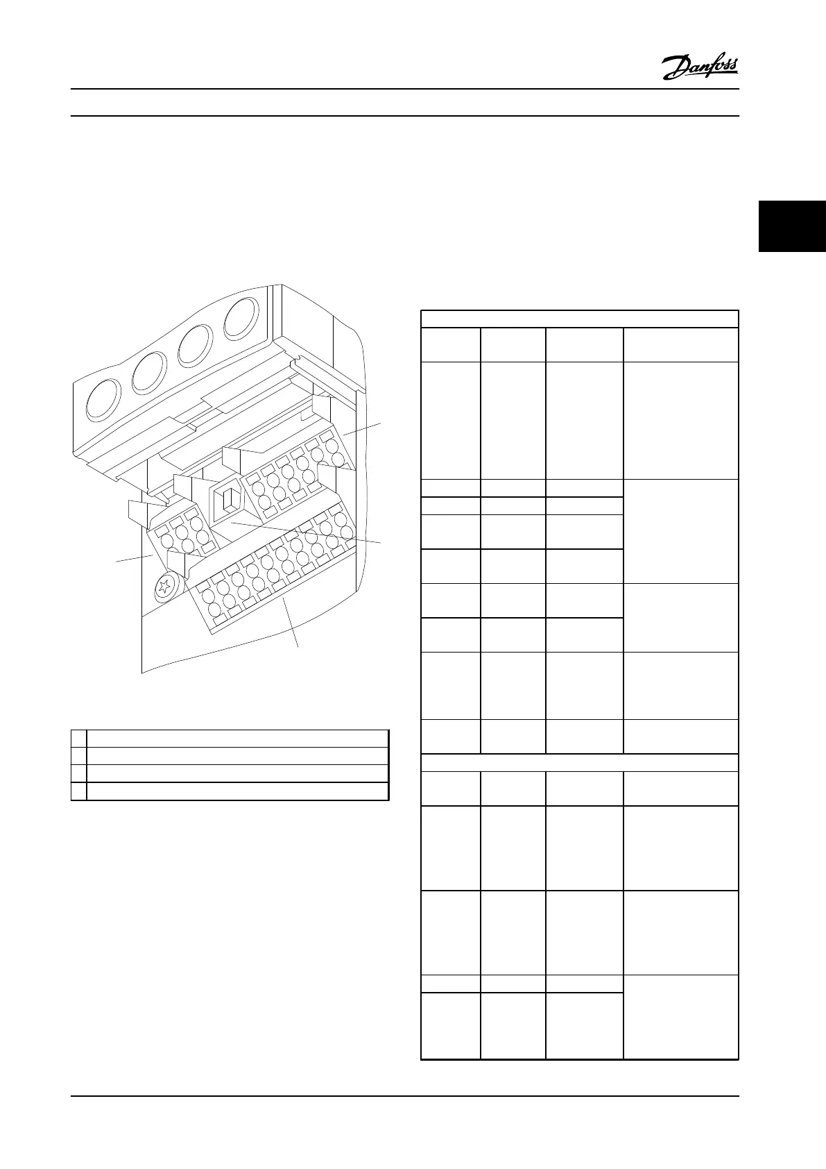
Figure 2.28 shows the removable adjustable frequency
drive connectors. Terminal functions and default settings
are summarized in Table 2.5.
61
68
69
39
42
50
53
54
55
12
13
18
19
27
29
32
33
20
37
Figure 2.28 Control Terminal Locations
1
Connector 1: Terminals 12-37
2 Connector 2: Terminals 61-69
3 Connector 3: Terminals 39-55
4 Connector 4: Terminals 1-6
Table 2.4 Legend to Figure 2.28
•
Connector 1 provides four programmable digital
inputs terminals, two additional digital terminals
programmable as either input or output, a 24 V
DC terminal supply voltage, and a common for
optional customer supplied 24 V DC voltage
•
Connector 2 terminals (+)68 and (-)69 are for an
RS-485 serial communications connection
•
Connector 3 provides two analog inputs, one
analog output, 10 V DC supply voltage, and
commons for the inputs and output
•
Connector 4 is a USB port available for use with
the adjustable frequency drive
•
Also provided are two Form C relay outputs that
are in various locations depending upon the
adjustable frequency drive configuration and size
•
Some options available for ordering with the unit
may provide additional terminals. See the manual
provided with the equipment option
See chapter 10.2 General Technical Data for terminal ratings
details.
Digital Inputs/Outputs
Terminal Parameter Default
Setting
Description
12, 13 - +24 V DC 24 V DC supply
voltage. Maximum
output current is 200
mA total for all 24 V
loads. Usable for
digital inputs and
external transducers.
18 5-10 [8] Start
Digital inputs.
19 5-11 [10] Reversing
32 5-14 [39] Day/Night
Control
33 5-15 [0] No
operation
27 5-12 [2] Coast
inverse
Selectable for either
digital input or
output. Default setting
is input.
29 5-13 [0] No
operation
20 - Common for digital
inputs and 0 V
potential for 24 V
supply.
37 - Safe Torque
Off (STO)
(Optional) Safe input.
Used for STO.
Analog Inputs/Outputs
39 -
Common for analog
output.
42 6-50 [100] Output
frequency
Programmable analog
output. The analog
signal is 0–20 mA or
4–20 mA at a
maximum of 500 Ω..
50 - +10 V DC 10 V DC analog
supply voltage. 15 mA
maximum commonly
used for potenti-
ometer or thermistor.
53 6-1* Reference
Analog input.
Selectable for voltage
or current. Switches
A53 and A54 select
mA or V.
54 6-2* Feedback
Installation Instruction Manual
MG16E222 Danfoss A/S © Rev. 2014-02-10 All rights reserved. 23
2 2
 Loading...


